 sjm4306
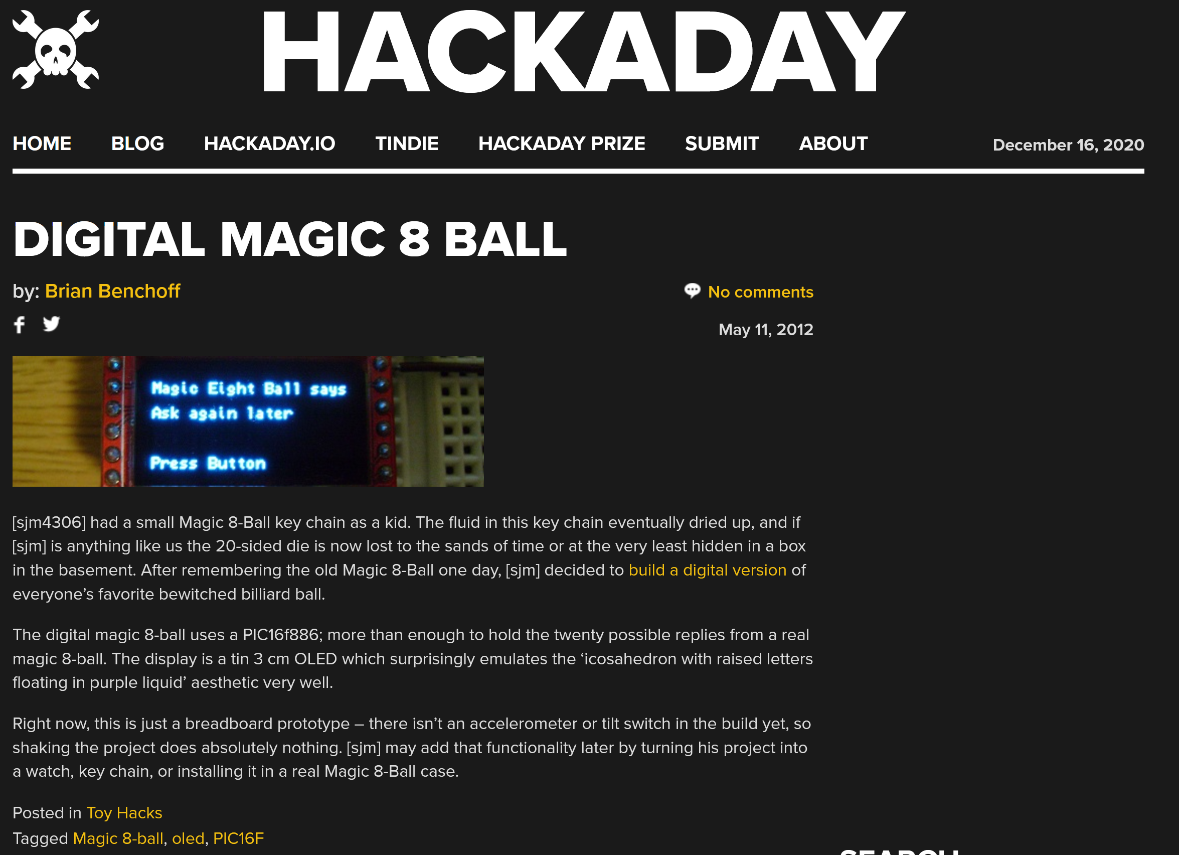
So way back in 2012 I wrote up a crude article on my blogspot about a breadboarded digital magic 8 ball project I created (http://diytronics.blogspot.com/2012/05/digital-magic-8-ball.html).
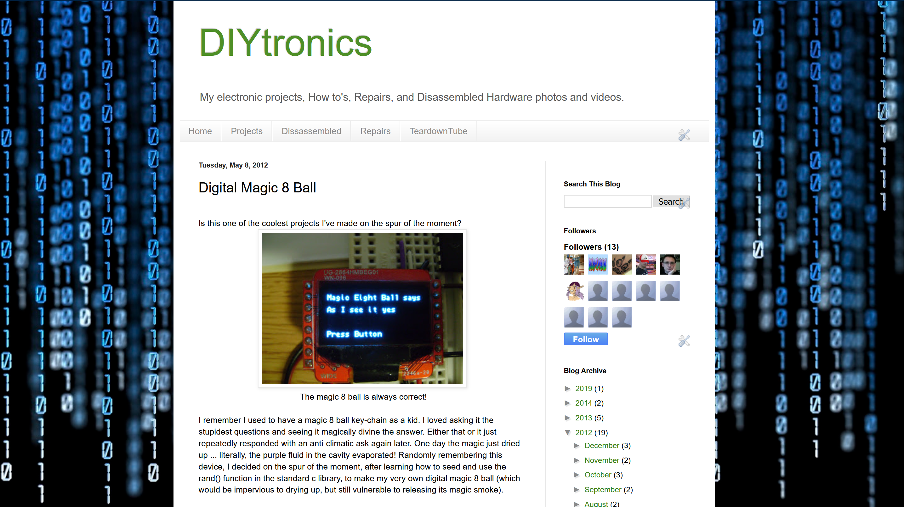
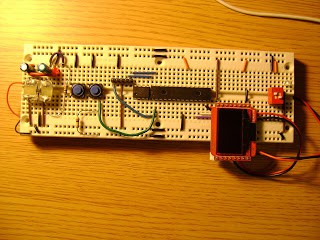
I just made the project on the spur of the moment while learning how to program for a new OLED screen I bought. To my surprise it was then picked up by HAD and became my first work that made it onto the site.
However, since then I was never satisfied with how I just left the idea unfinished and unpolished. So that brings us to now, I wanted to create a nice pcb for the project and add some niceties to the software/user interface. And given how much of a trainwrech 2020 has been I thought it'd be a nice way to send off the year and predict whether 2021 would be better!
As with many small projects I just copied and pasted a minimum required part selection from a past project to get started.
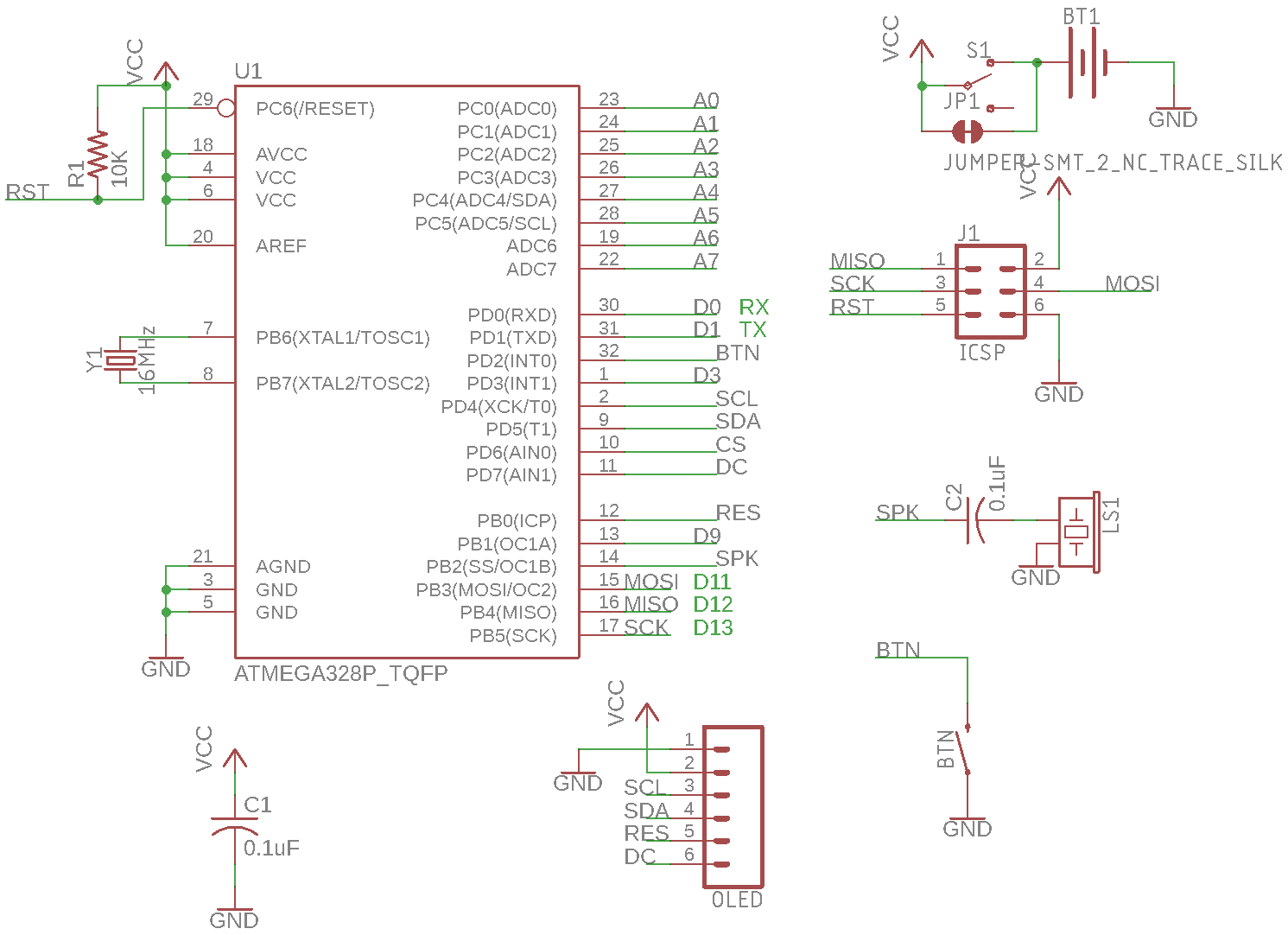
I first decided on the shape of the board. Clearly since it was modeled after an 8 ball the pcb would have to be round. Additionally, taking some inspiration from tomagochis of the 90s/00s, I wanted to have it be keychain sized and the screen to be nicely centered. Back when I did the original prototype I dreamed of adding an accelerometer to detect a user shaking to initiate the fortune telling but I decided to scrap that idea in favor of a single button, both cheaper and simpler. Powering the device would be a single CR2032, cheap and widely available. Finally I wanted only the one button so I decided to use the microchip's lowest power sleep mode for soft power control that could be woken with a button press and would sleep after a short delay of no user input.
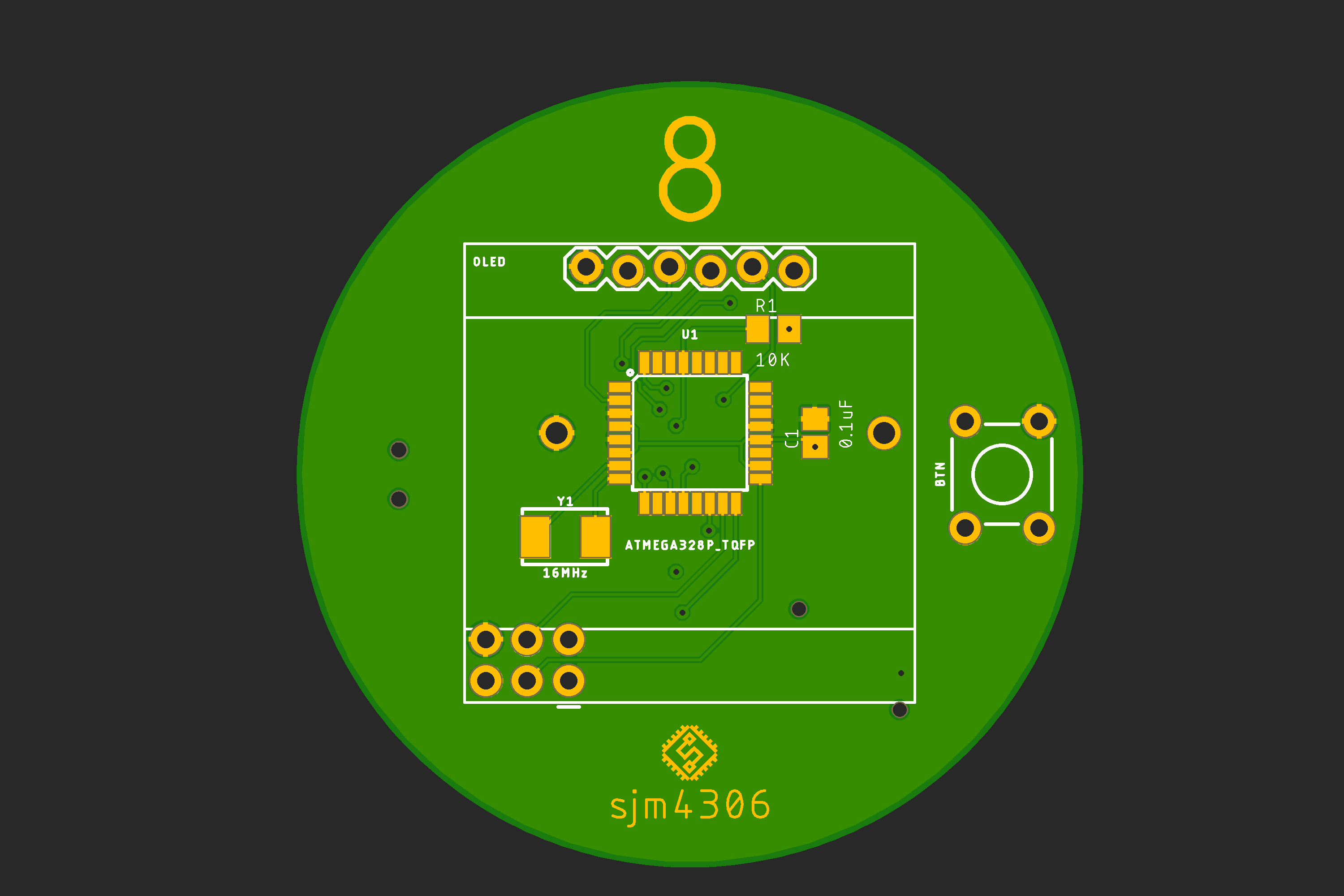
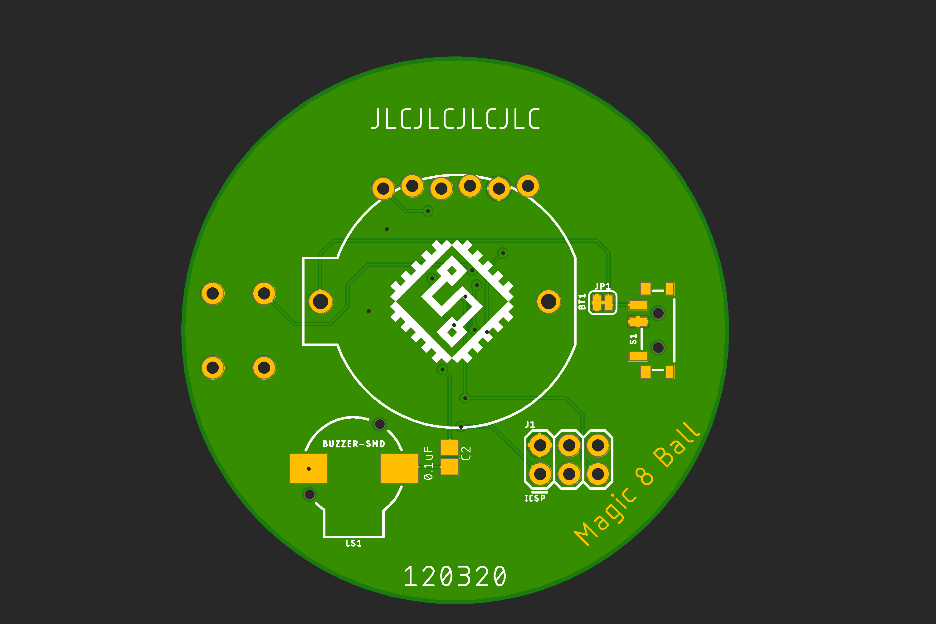
So with these general design choices in hand I threw together a board. Since the layout was pretty sparse and cost optimized I decided to throw in some optional extra features: a slide switch to manually disconnect the battery for longer storage and a small speaker to bleep/bloop when the button was pressed.
Luckily since the parts list is quite simple I pretty much already had most everything in my hoard (erm I mean collection). I intend to gift the finished device so I needed the board at least a week before the 25th so I rushed off to JLCPCB to place the order and have them rushed back to me. On the 15th of December they arrived and in the next log I'll document assembling, the software and testing the first revision.
Discussions
Become a Hackaday.io Member
Create an account to leave a comment. Already have an account? Log In.