 sjm4306
Special Thanks to JLCPCB for sponsoring this project. JLCPCB Prototype for $2 (Any Color): https://jlcpcb.com
The board finally arrived so I rushed to assemble one to test. I filmed the process in usual fashion and to demonstrate the functionality.
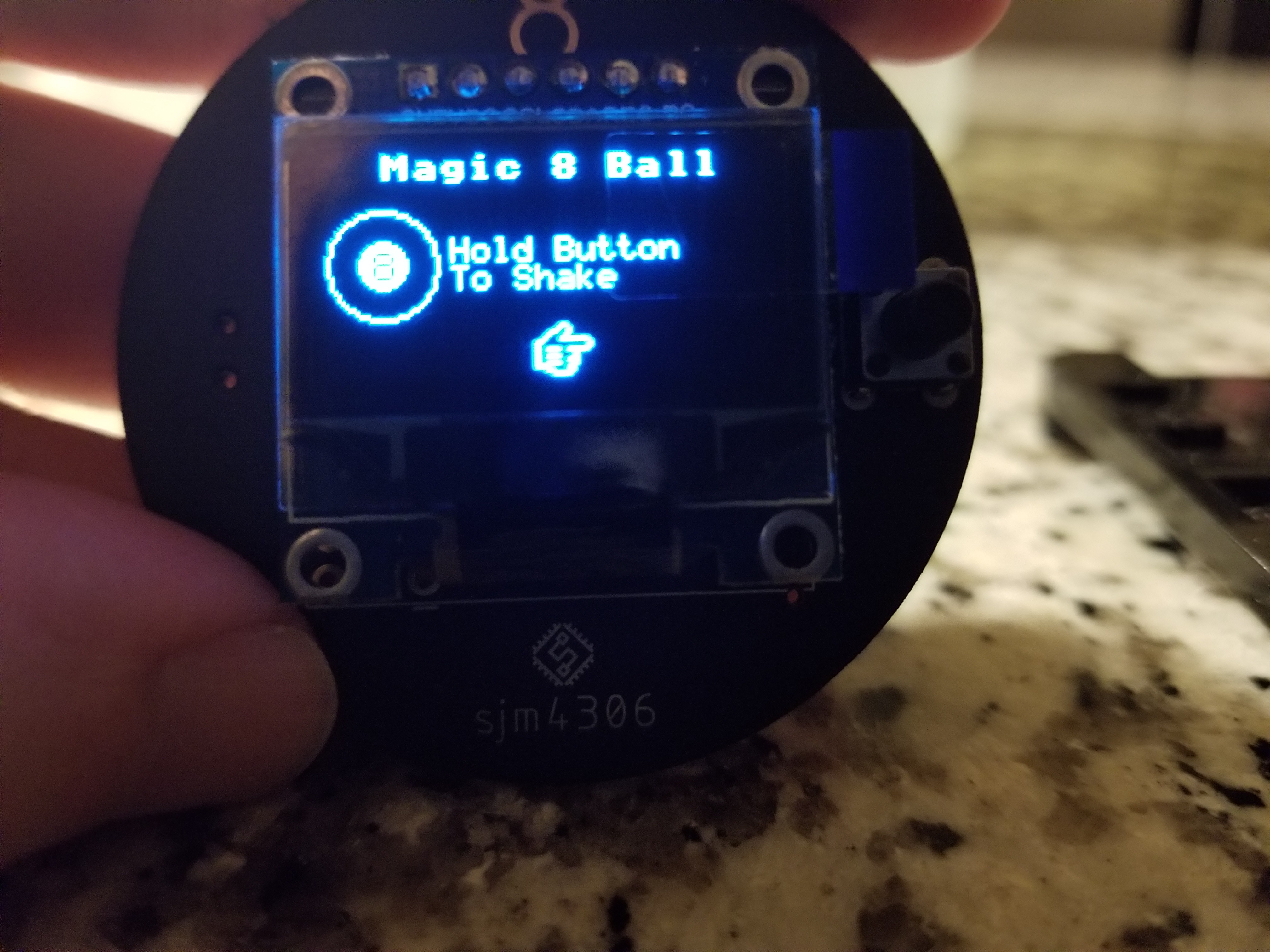
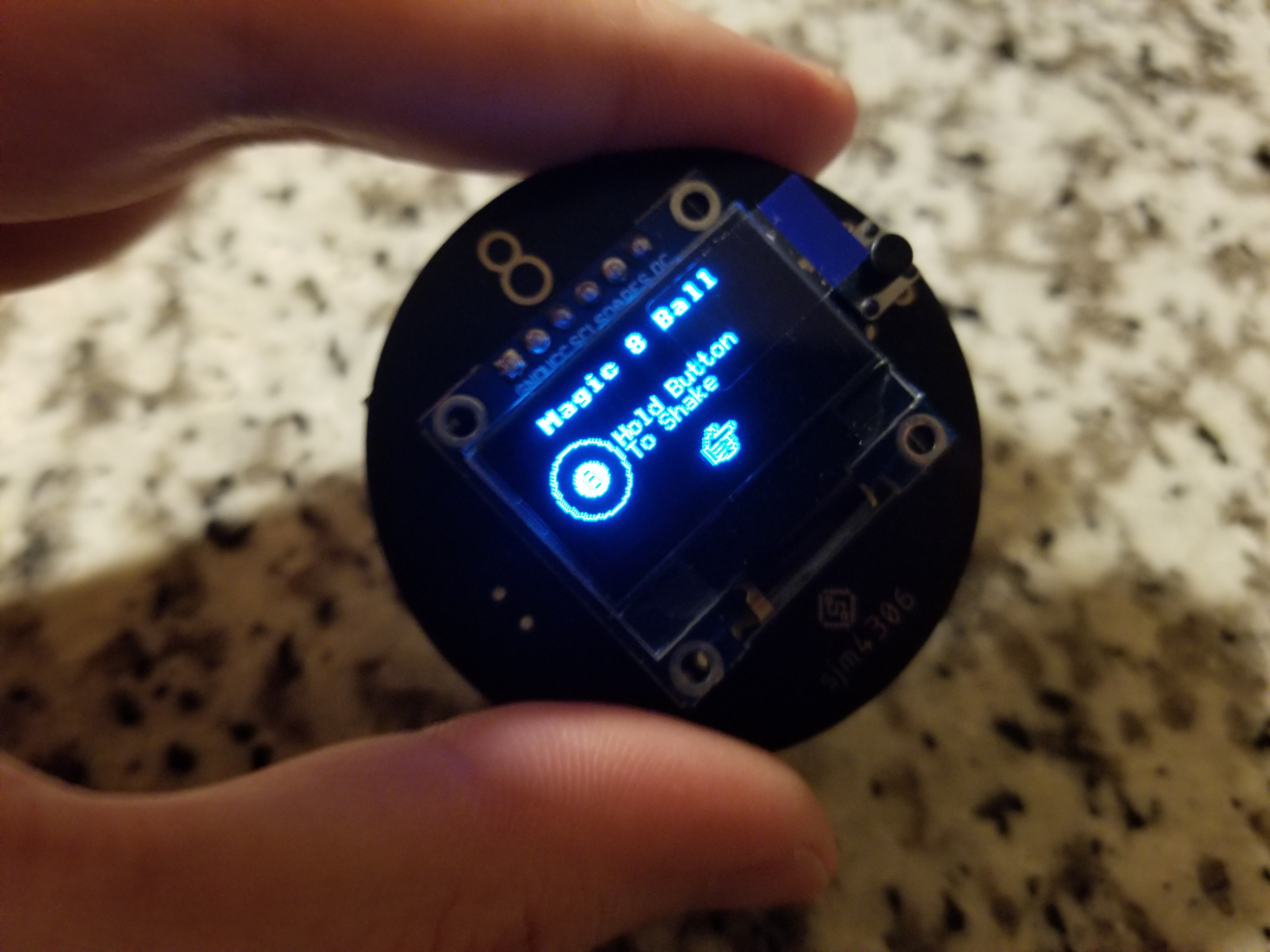
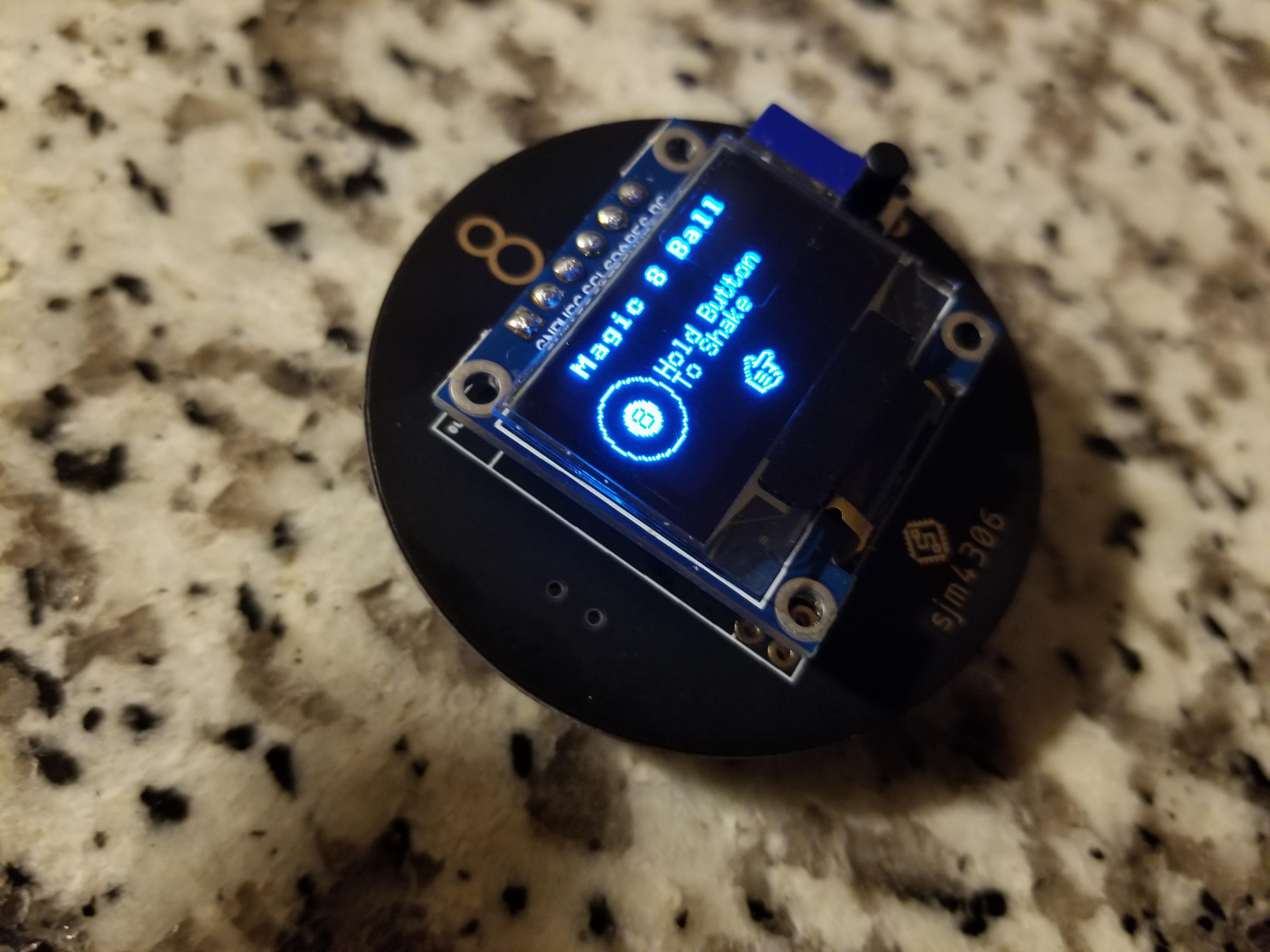
Here's a few glamor shots of the assembled pcb working.
I didn't really go into detail how the software works in the video so we can explore that now. I drew a simplified flow chart to illustrate what the software generally does
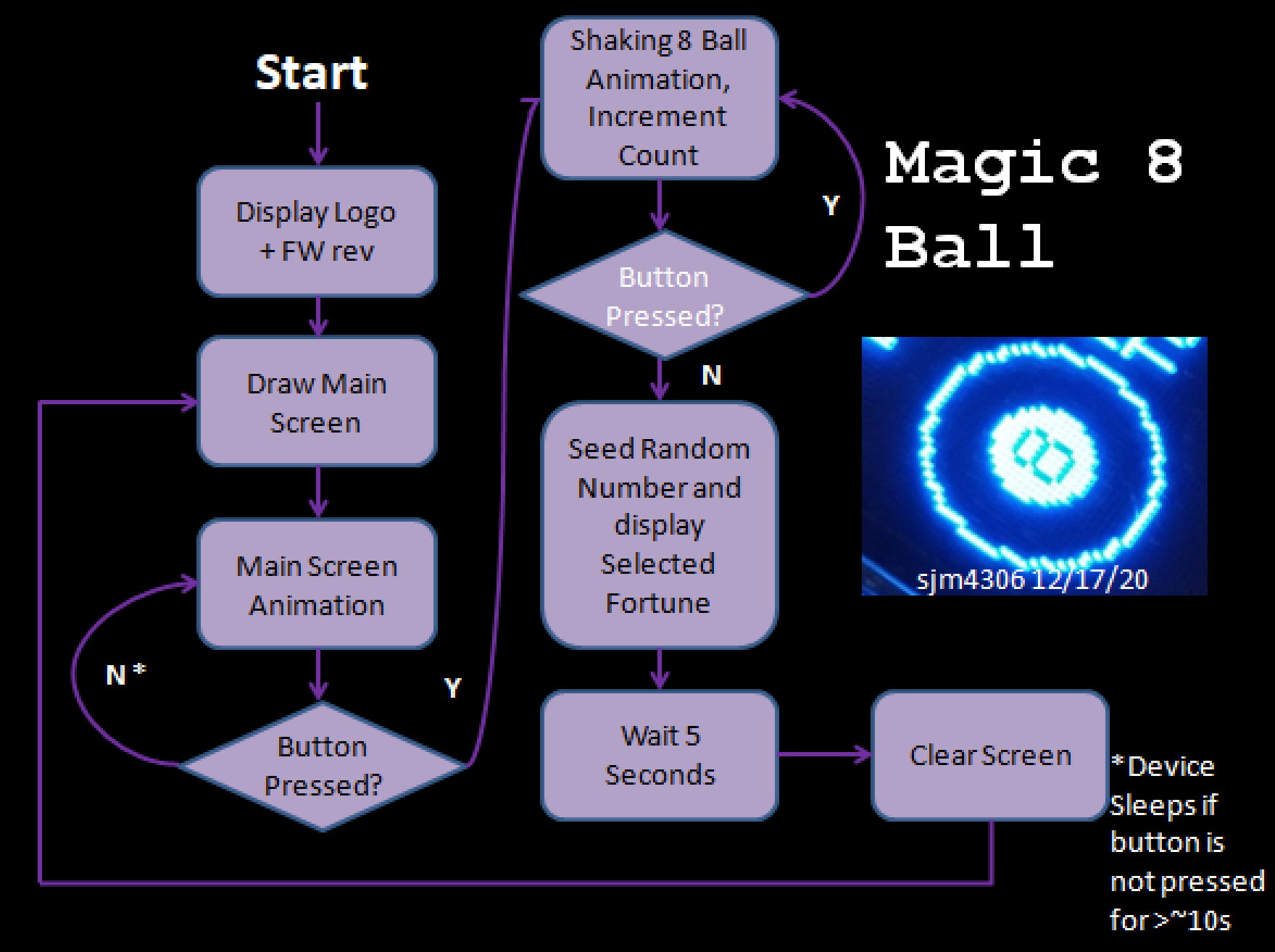 The software is fairly simple with really only three main modes: the main screen, telling a fortune, and sleep. The transition between each mode is initiated as shown in the diagram above.
For selecting a random fortune to display, I opted for the age old psuedo-random function (basically a glorified linear feedback shift register). The main issue though is while seemingly random, without seeding a different value the sequence will always be the same. To get around this I count the length of time the user presses the button (and mask this by having them hold it to "shake" the 8 ball with accompanying animation) in order to seed the random function with a different value each time.
Now after assembling the first board I've found some things that could be further improved. For starters I didn't think about the battery holder placement and it currently blocks access to the OLED pin solder pads on the back so the screen must be soldered from the front. PCB rev 2 will have the battery holder moved down so that the pads are exposed and easily solderable from the back. Additionally I found that even in the deepest sleep state the atmega supports, the device draws somewhere near 30uA. While not horrible this means with a standard ~220mAh CR2032 battery, it will only last just short of a year on standby.
I have a feeling much of that is due to the OLED being permanently connected to the battery and relying on its own controller's sleep functionality. In the next revision I'll probably power the OLED supply pin directly from one of the atmega's outputs so it can be completely turned off during power down.
Now as for the final cherry on top before giving this to the recipient, I plan on 3d printing a little case to pressure fit the pcb into so it's better protected. The design for that will be covered in the next log.
Discussions
Become a Hackaday.io Member
Create an account to leave a comment. Already have an account? Log In.