 Bud Bennett
I was nearly set to accept the second pass design as the final product until I started thinking about other stuff that could go wrong. I revisited the issue of when the user accidentally misconnects the balance leads between two batteries. I was completely wrong in my previous thinking that the balance lead PFET switches would survive -- they won't without some help. The problem doesn't become clear until you analyze what happens when three, or more, batteries are connected to the station and two of the batteries have misconnected balance leads. (The details section of this project must be corrected.)
Even before the charger is enabled, there is a problem. The lowest voltage battery will draw current from BAT1 and connect its balance leads to the charger balance leads. If two batteries have misconnected balance leads then it is possible for the battery with the higher voltage to have its balance leads connected to the lower voltage battery -- very bad.
What happens then is that the higher voltage battery dumps current into the low voltage battery without regard to any current limit. Fortunately, the internal battery resistance comes into play and the two batteries connect and disconnect at a rapid frequency until the voltages equalize, or the PFETs overheat and fail.
Things get worse when the charger begins charging the connected batteries. The added charger current tends to inhibit the internal battery resistance from disconnecting the balance leads and the PFETs fail quickly.
I verified the above scenario with simulation and experiments on the bench with controlled battery voltages. It's not pretty.
*************************
I think there is a solution. I added a comparator to sense if the first cell of a battery is above the voltage on the first cell balance lead that is connected to the charger and prevent the PFET switches from closing. This is a schematic of one of the channels with the comparator in place:
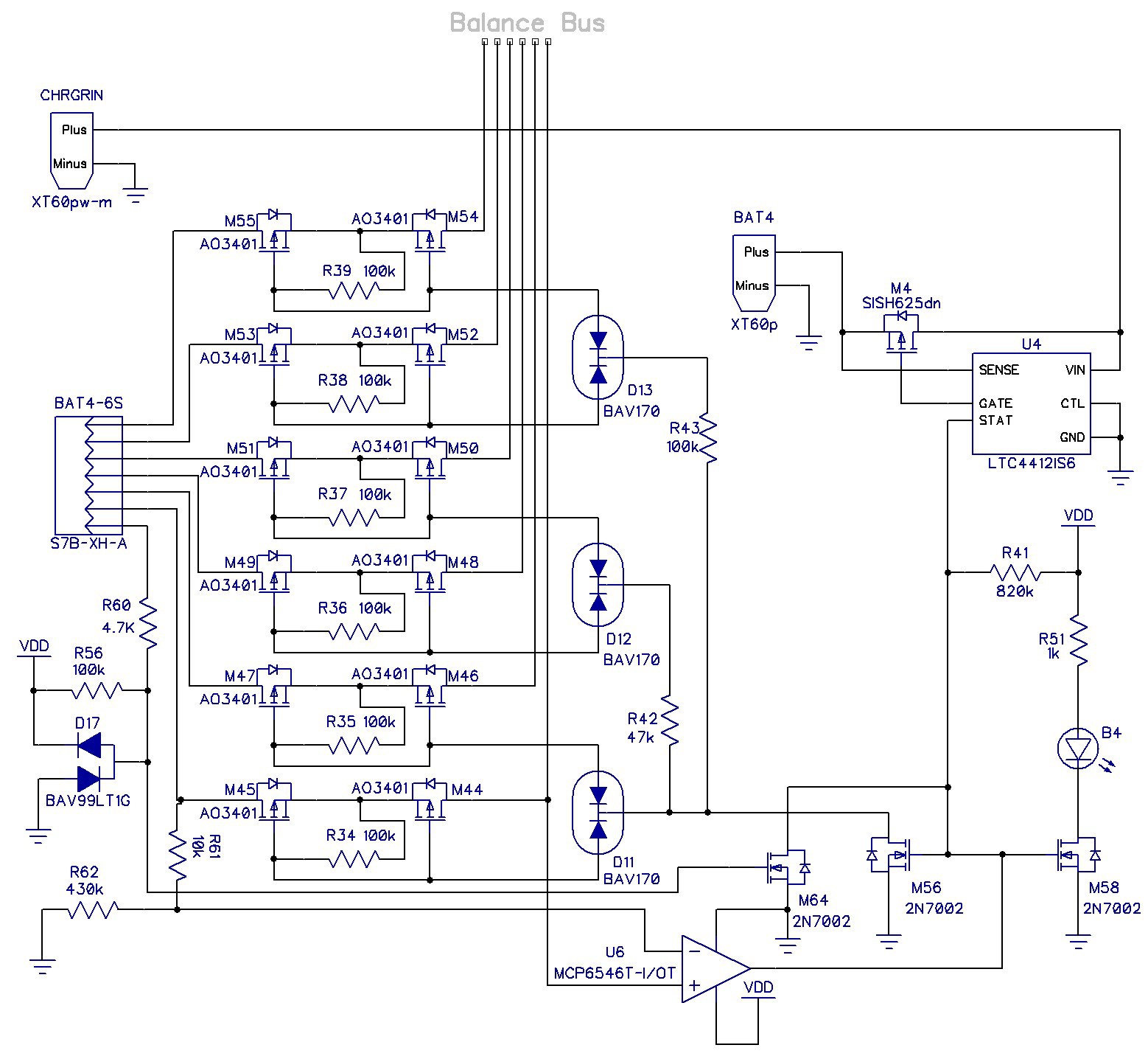
The MCP6546 is relatively cheap, open-drain, comes in a SOT23-5 package, and has built-in 3mV hysteresis. R61 and R62 create a voltage drop of between 70mV-100mV. If the batteries first cell voltage is higher than what is on the balance lead bus then the comparator pulls down on M56 and prevents the PFET switches from connecting. It's not foolproof. The battery voltages will eventually equalize and the PFETs will get connected, but there will be much less voltage and current to deal with so the PFETs should survive.
I seems to function correctly. I simulated it in LTspice with the schematic below:
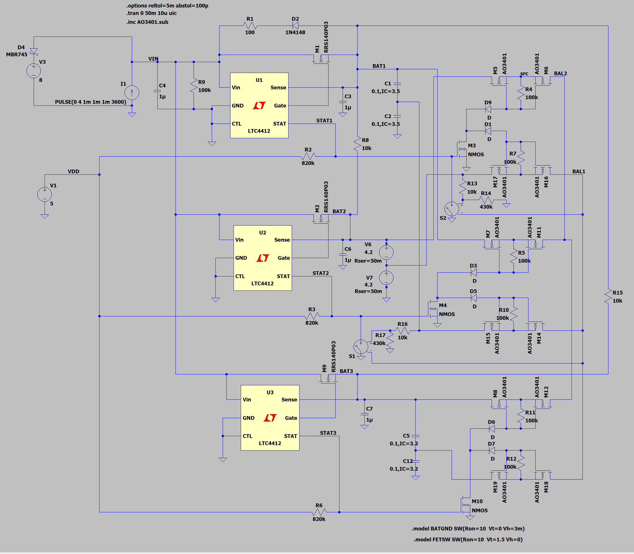
A full blown implementation is too simulation intensive, so I simplified it a bit. The comparators are implemented with voltage controlled switches, S1 and S2.. I also had to use generic NMOS devices and diodes because the more complicated models were generating artifacts in the simulation. The charger is located in the upper-left -- just a current source and voltage clamp. I modeled the 2-cell batteries with large values of capacitance with 25m-50m Ohm series resistance tagged with an initial voltage condition.
The result of the simulation is shown in the plots below:
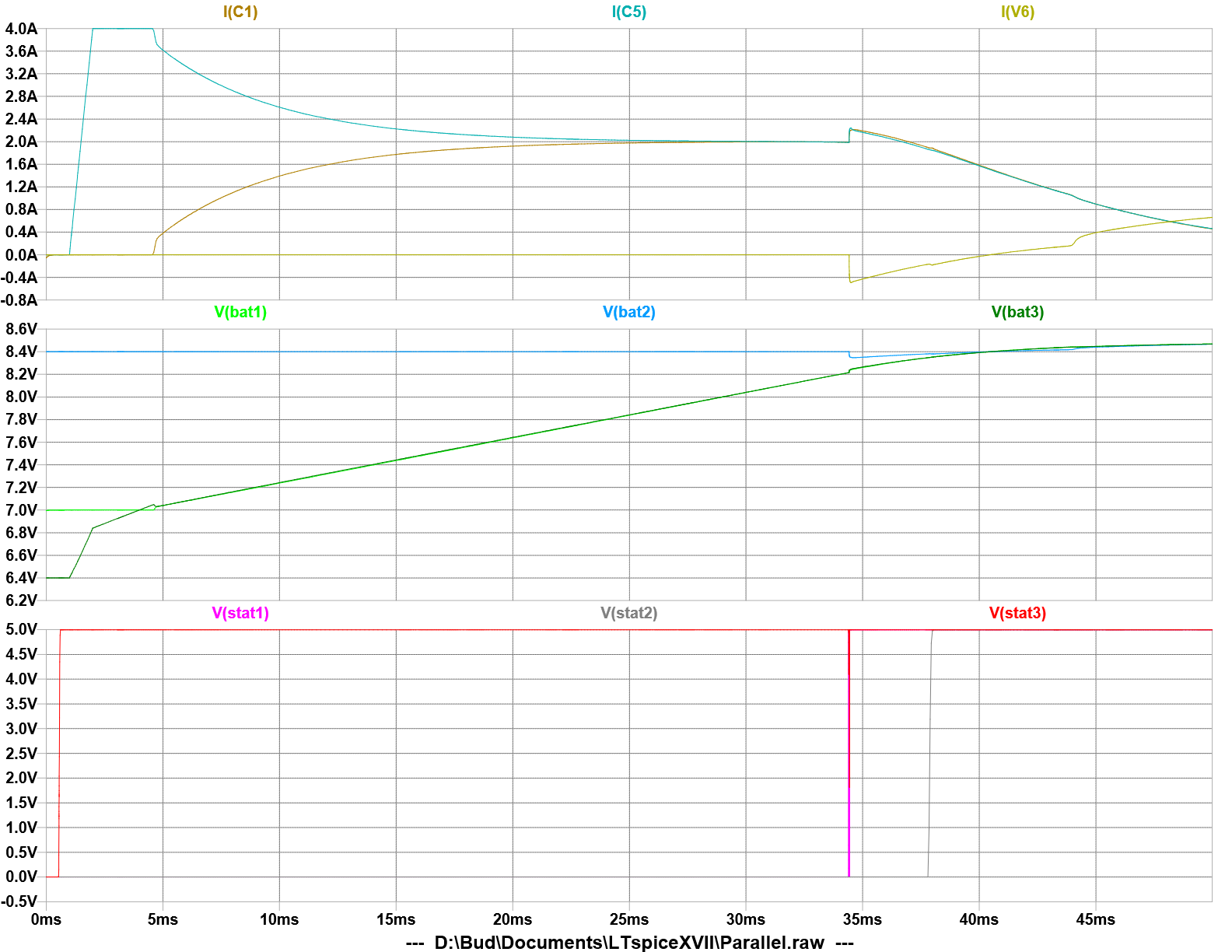
The full charging cycle takes place in 50ms. When the charger is engaged at 4A, it begins to charge the battery with the lowest voltage, BAT3, at full current. When BAT3 rises to 3.5V/cell the current begins to share with BAT1, but BAT1's STAT pin is held low by the comparator. This is normal charging operation because the STAT pin doesn't affect the behavior of the LTC4412. Note that BAT1's balance leads are not connected to the balance lead bus. Neither are BAT2's balance leads connected due to the mis-wiring.
When the voltage of the two batteries gets within 200mV of BAT2 (at about 34ms) the comparator allows the balance leads to connect and STAT1 is asserted. This causes current to flow from BAT2 into the other two batteries through the balance leads. Note also that the charger is not charging BAT2 at this point since its voltage is not equal to or below the other two batteries. The current through the PFET switches is less than 0.5A, which they can survive as a continuous condition with only 12.5mW of power dissipation. The balance leads of BAT1 are still not connected because the LTC4412 for BAT2 has not asserted its STAT pin.
The charger continues to charge the batteries until the voltage equalizes on all three batteries (at about 38ms). Then the STAT2 signal goes high and now all the balance leads are connected. The charging cycle will complete normally now.
Other Pass 3 changes:
I decided to add some circuitry to inhibit the charge LED indicators from lighting up if there was no battery present. There is a pullup resistor, R56, connected to the GND pin of the balance lead connector. The voltage at that pin feeds the gate of a 2N7002 NMOS transistor, M64, with it's drain connected to the STAT pin of the LTC4412. If there is no battery present M64 keeps the balance leads disconnected and the LED turned off. This is also helpful if the balance leads are attached before the battery lead since no current can flow inadvertently through the balance leads until the battery is connected to GND.
R60 and D17 provide ESD protection for M64.
Discussions
Become a Hackaday.io Member
Create an account to leave a comment. Already have an account? Log In.