 Bud Bennett
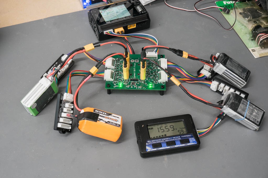
I received 5 populated boards from JLCPCB yesterday afternoon. I decided not to fully populate these boards since I had accumulated a few previous revision boards that had many of the components that I needed to make this one. Scavenging parts saved a bit of money.
I soldered the PIC into the board without programming it beforehand. After a bunch of errors, I finally succeeded in programing it in-situ...and it works!
This morning I began functional testing. It works well with both my SkyRC Q200 charger and my ToolkitRC M6D charger. It passed all of the simple tests, like adding batteries as they began to match voltage and draw current. The LED light when a battery comes online and turnoff when charging terminates.
It also passed a couple of tests for swapped battery survival. The tests involve three batteries: 2 with a low state of charge and another with a high state of charge. In the first test the lowest charge state battery connected with a swapped balance lead to another battery. The charger flagged a mismatch in the balance leads and refused to charge. The second test had the lowest voltage battery correctly plugged in with its balance leads and the other two batteries had swapped balance leads. When the charger began to charge the lowest battery was correctly connected to the balance leads, but the other two batteries had to wait until they were within 100mV before the balance leads were connected. It all worked the way it was supposed to.
I tested some parametrics:
Quiescent Current Draw (from BAT1): 130uA, 3S battery no balance leads connected.
Current Draw from BAT1 when BAT1 LED lit: 1.3mA, PIC is running @ 1MHz clock, 50uA draw from battery detection circuit, LED#1 is lit (425uA).
Current from BAT1 when charger input shorted: 13.3mA. This low current is because I used A BSS139 depletion mode MOSFET instead of a 100R resistor between the charger input and BAT1.
Ready for Prime Time:
I can't find anything really wrong with this design. I do have a short list of possible issues:
- It doesn't really work with 1S batteries. That is not a problem for me since I don't plan on using it for small 1S micro-drone batteries. The basic problem is that 1S batteries aren't equipped with any balance leads. If the balance leads are not plugged into the parallel charging station, the batteries will still charge but the LED indicators won't light up. So the user won't know which batteries are charging.
- If the user decides to not connect balance leads the LEDs won't light up. I don't believe this is a real problem for anybody, but time will tell.
Discussions
Become a Hackaday.io Member
Create an account to leave a comment. Already have an account? Log In.