 Bud Bennett
[Edit 2021-09-18: Changed resistor types to all 1206. Hopefully, this will help future proof the circuit to work with a larger assortment of chargers.]
I screwed up.
I calculated values for R1, R4, R6, R8, R10 and R12 based upon cell voltage differences instead of voltage tap differences. I also forgot to consider how a dead battery cell would affect power dissipations in these resistors. And just for good measure I did not bother to investigate how large these values could get before the ToolKitRC M6D charger would fail its checking algorithm.
Worst Case Survival:
The resistors that I referenced above are used to provide a relatively low resistance between the charger input and the balance leads of BAT1. When the charger checks for voltage and/or resistance to the balance leads it should be satisfied with the measurement it makes. (More on that later.) But the resistors should be able to survive worst case voltage difference between batteries and faulted batteries.
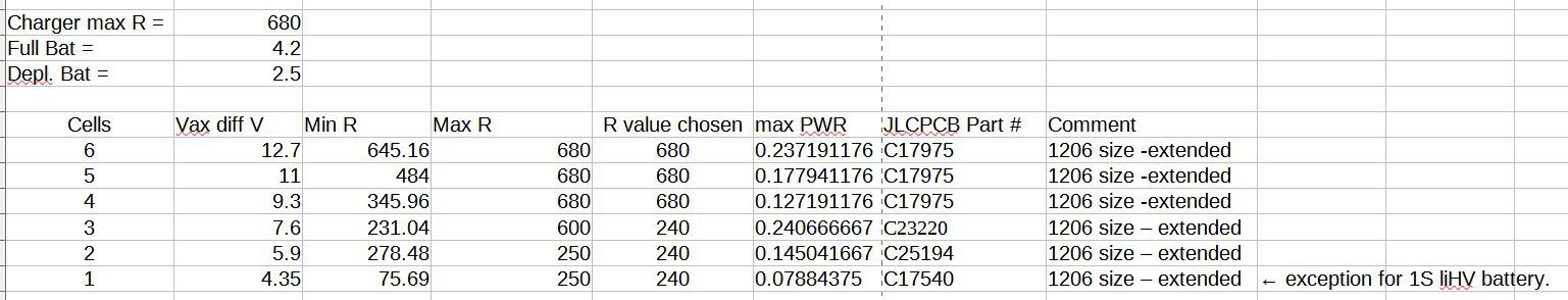
I consider a worst case condition is when a fully charged Li-Ion battery is plugged into BAT1 and a fully depleted battery with a dead cell ( a dead cell has zero volts across it) inserted into any other slot. A fully depleted Li-Ion has about 2.5V/cell, where a fully charged Li-Ion is 4.2V/cell. So the maximum voltage between each tap of the balance leads is given by:
Vmax = N*4.2V - (N-1)*2.5V, where N = Cell count at tap.
This voltage difference should not damage the resistor. By that I mean that it should not exceed its power rating. Typical power ratings of standard SMD resistors sizes are as follows:
0603 = 0.1W, 0805 = 0.125W, 1206 = 0.25W, 1210 = 0.5W, 2512 = 1W.
I chose to use 1206 size for all six resistors. So to get the minimum resistor value just divide the square of Vmax by its power rating. I did a spreadsheet to get the resistor values:
The ToolKit M6D maximum balance lead resistance test:
I was lazy when I selected 75R resistors to satisfy the charger. I knew that 1k was too large so I just tested 100R and it worked. Good enough, eh? Well, it was a bad assumption. I went back and inserted a potentiometer for R12, R10, R8 and R4 and varied it to find out what value the M6D considered a failure -- it was around 750R for R4 (10X higher than I was using), 590R for R8, and 240R for both R10 and R12. When you put this piece of information along with the above power dissipation limits then values and sizes in the above spreadsheet.
R1 = 680R, 1206 size
R6 = 680R, 1206 size
R4 = 680R, 1206 size
R8 = 240R, 1206 size
R10 = 240R, 1206 size
R12 = 240R, 1206 size
These large size resistors incur a $3 SMT Assembly setup fee for each value. I am using only two values to keep the setup fees to a minimum.
The Vmax = 4.35 for a single single cell is for LiHV chemistry. LiHV is not used for higher cell counts because it doesn't generate maximum voltages worse than Li-Ion.
Revision 4 Here We Come:
The size changes will force a PCB revision. I will also use this revision to flip the XT60PB connector from the bottom of the board to the top, to make it easier to design an enclosure for this board. I'm not sure that I will build Rev4, but I will update the files when the PCB changes are complete.
Discussions
Become a Hackaday.io Member
Create an account to leave a comment. Already have an account? Log In.