 Evan Li
I've recently become the co-owner of a 1972 Porsche 914 with a 5.7L LS1 swap. As a result of the shift from air cooled to water cooled, the car required the addition of a gauge for coolant temperature. An oil pressure gauge was also added and the two gauges sat together, mounted on the floor near the shifter. It didn't look great.

Quad gauges were a popular alternative to the stock fuel combo gauge, but were hard to find or quite pricey. I set off to build my own using a salvaged Porsche 944 fuel gauge and a spare 914 combo gauge.
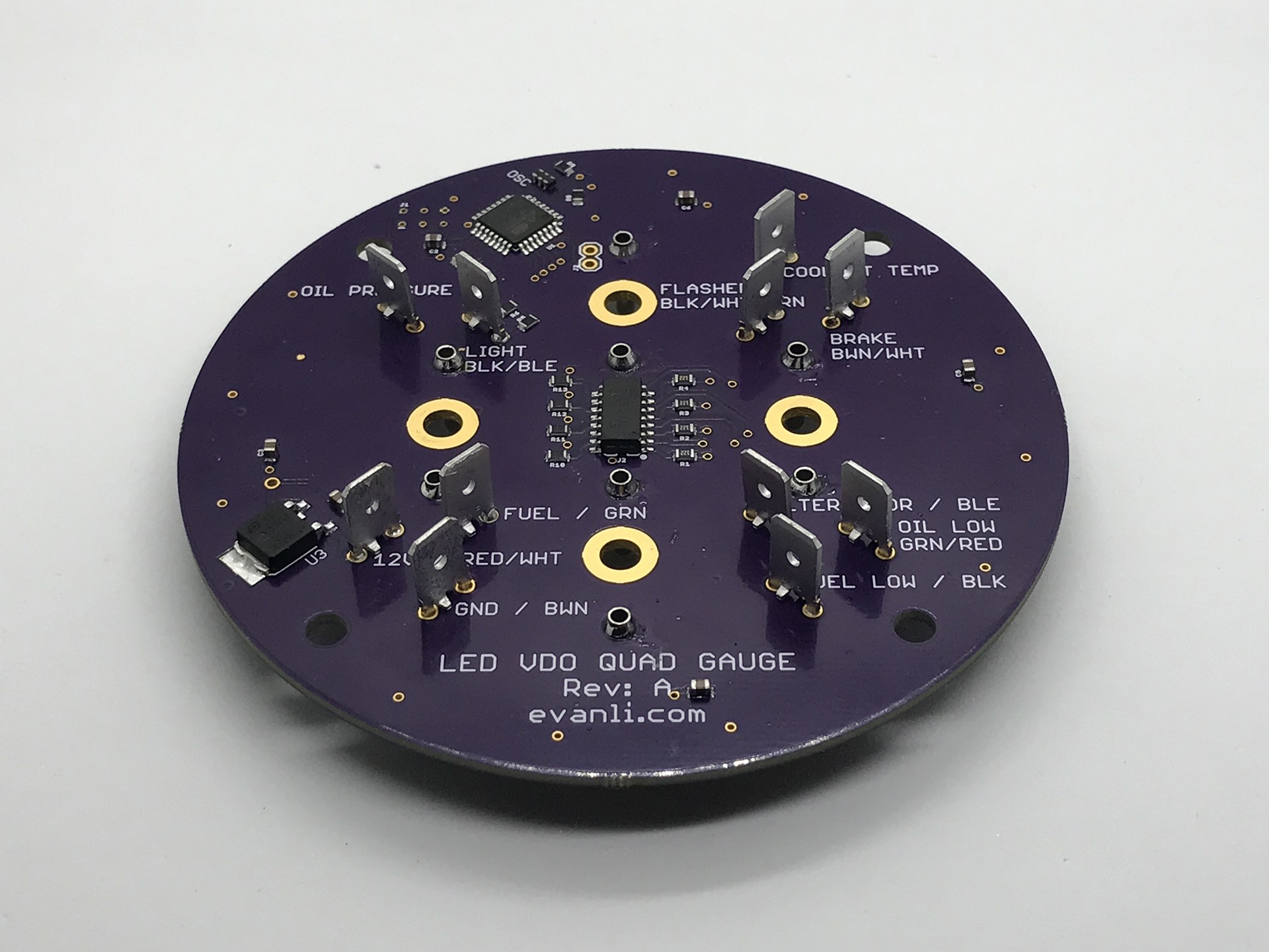
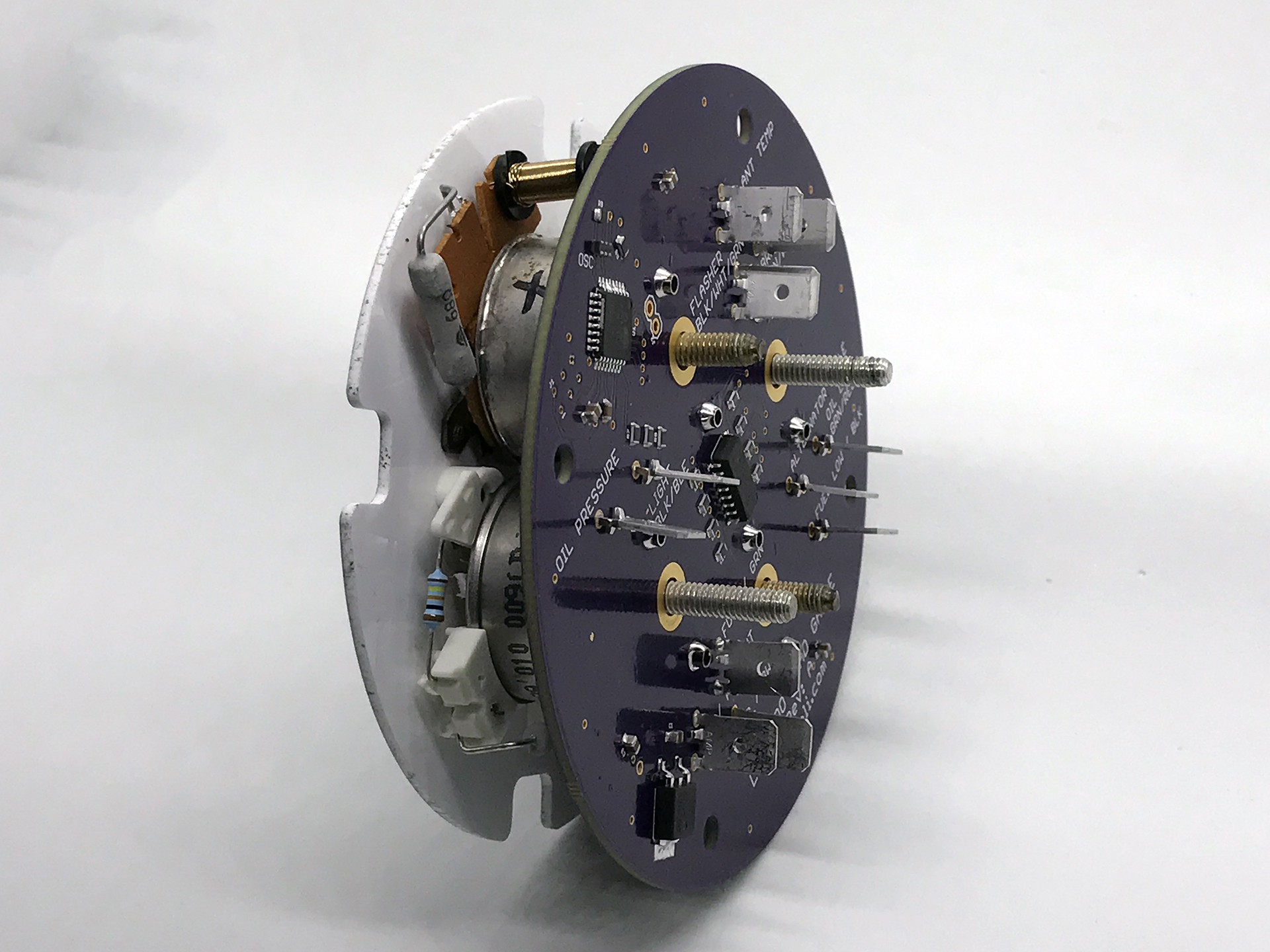
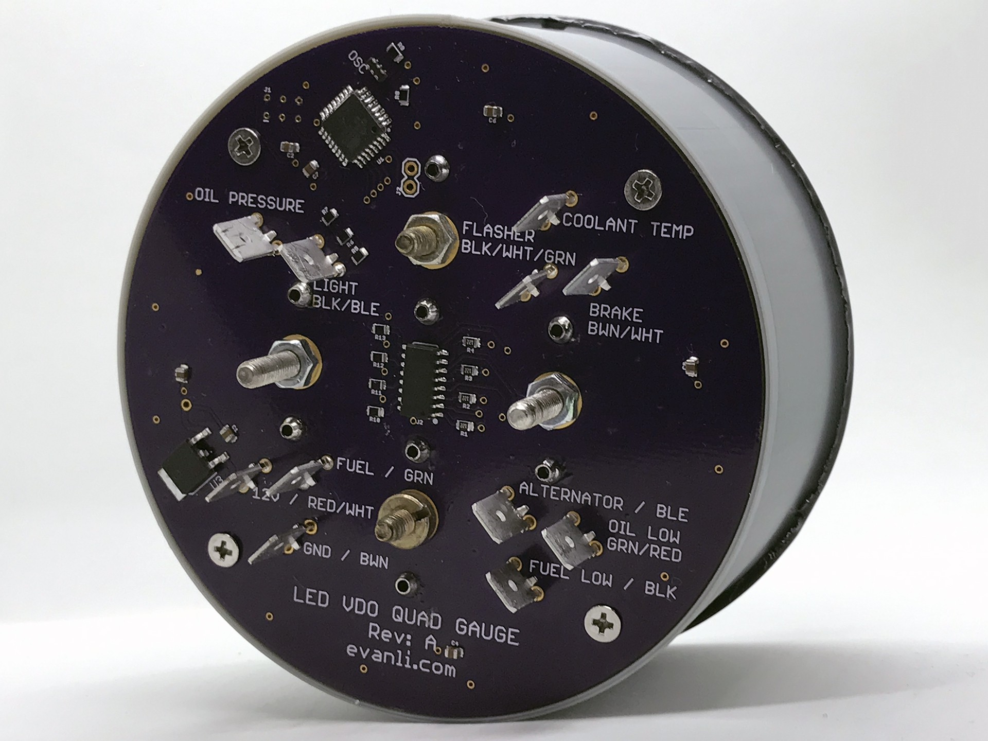
Rather than just stick a bunch of VDO gauges together in a shell, I wanted to preserve the indicator lights for the generator, low oil, low fuel, and parking brake. This resulted in a custom PCB that would plug into the existing wiring in the car and connect to the VDO gauges. All inputs from the car are optoisolated. An ATMega328PB at 16Mhz powers the operation. Overkill for this application, but it's just so damn easy to use. A LDO voltage regulator provides 5V power by stepping down the 12V from the car.
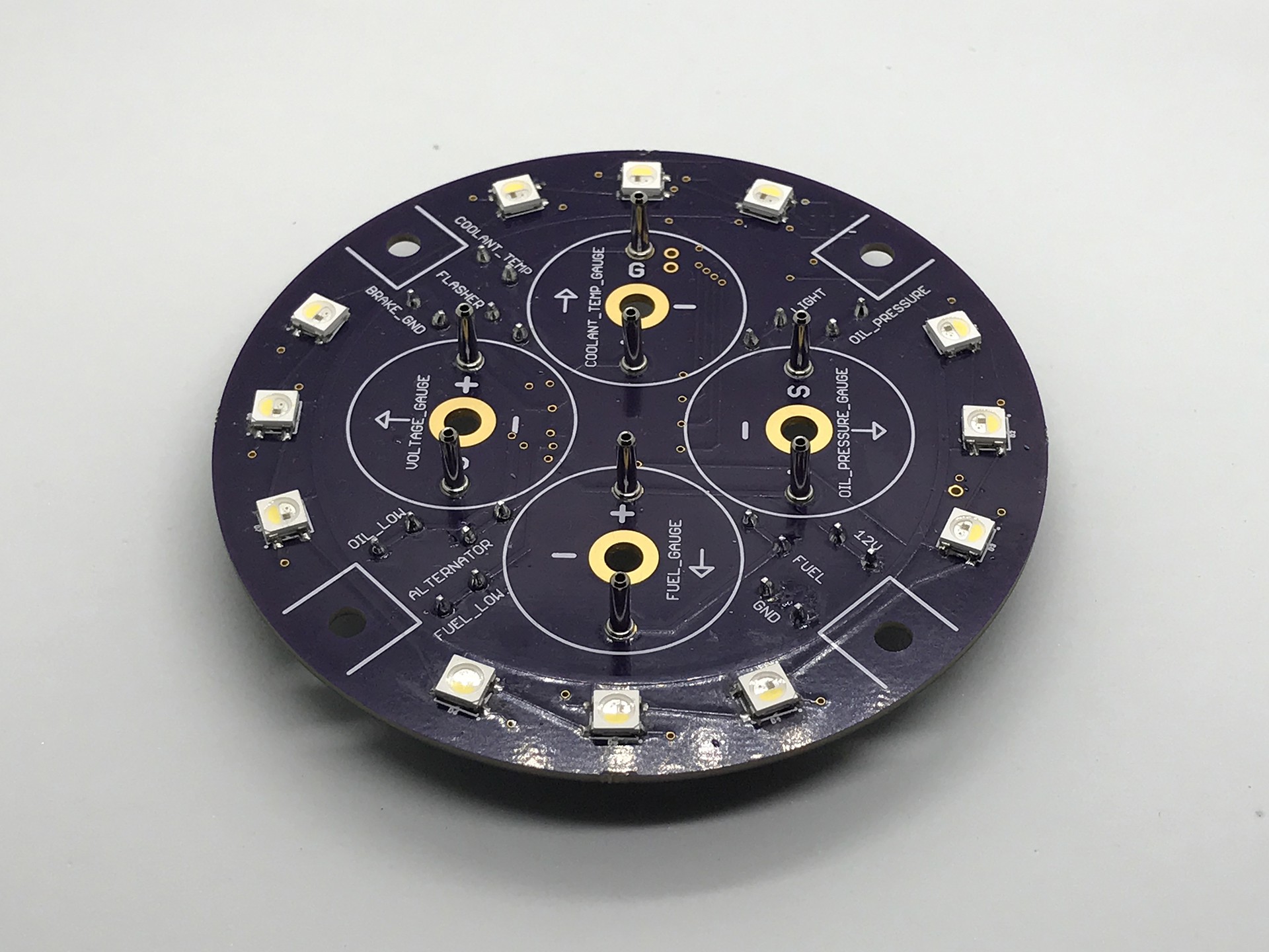
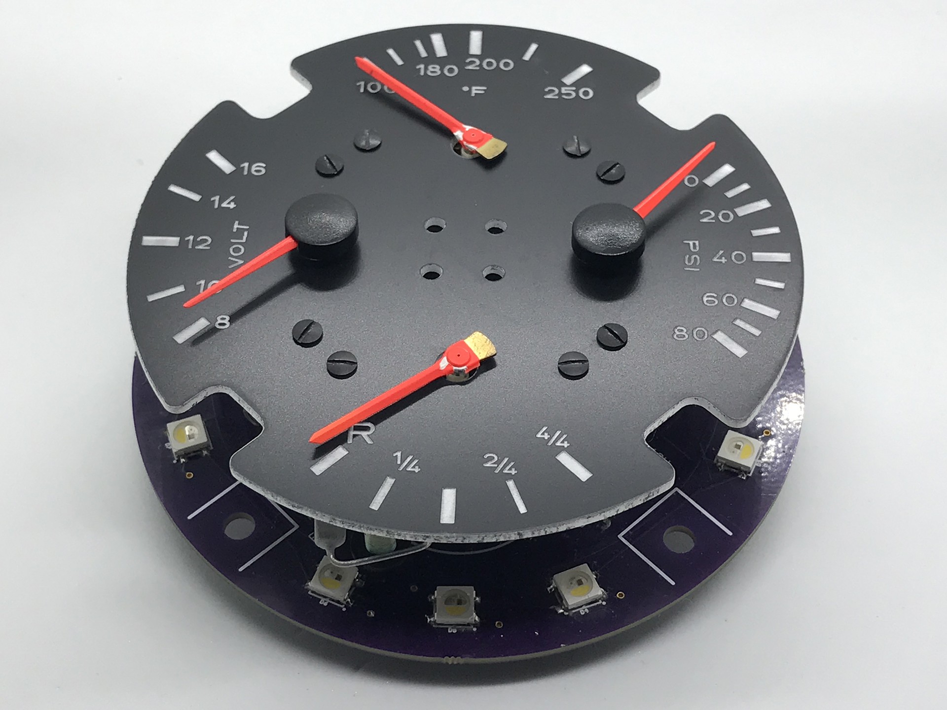
In order to light the gauge and provide indicators, 12 SK6812RGBW LEDs were used. They are controlled by the microcontroller via a 1 wire serial protocol, which allows for full RGBW control. The ability to individually address the LEDs allows them to act as both lighting and indicators. The VDO gauges insert directly into the PC pins on the board, and the board uses two styles of VDO gauges. An older style gauge, which was salvaged from the 944 fuel gauge, and a new style gauge which was purchased off the shelf.
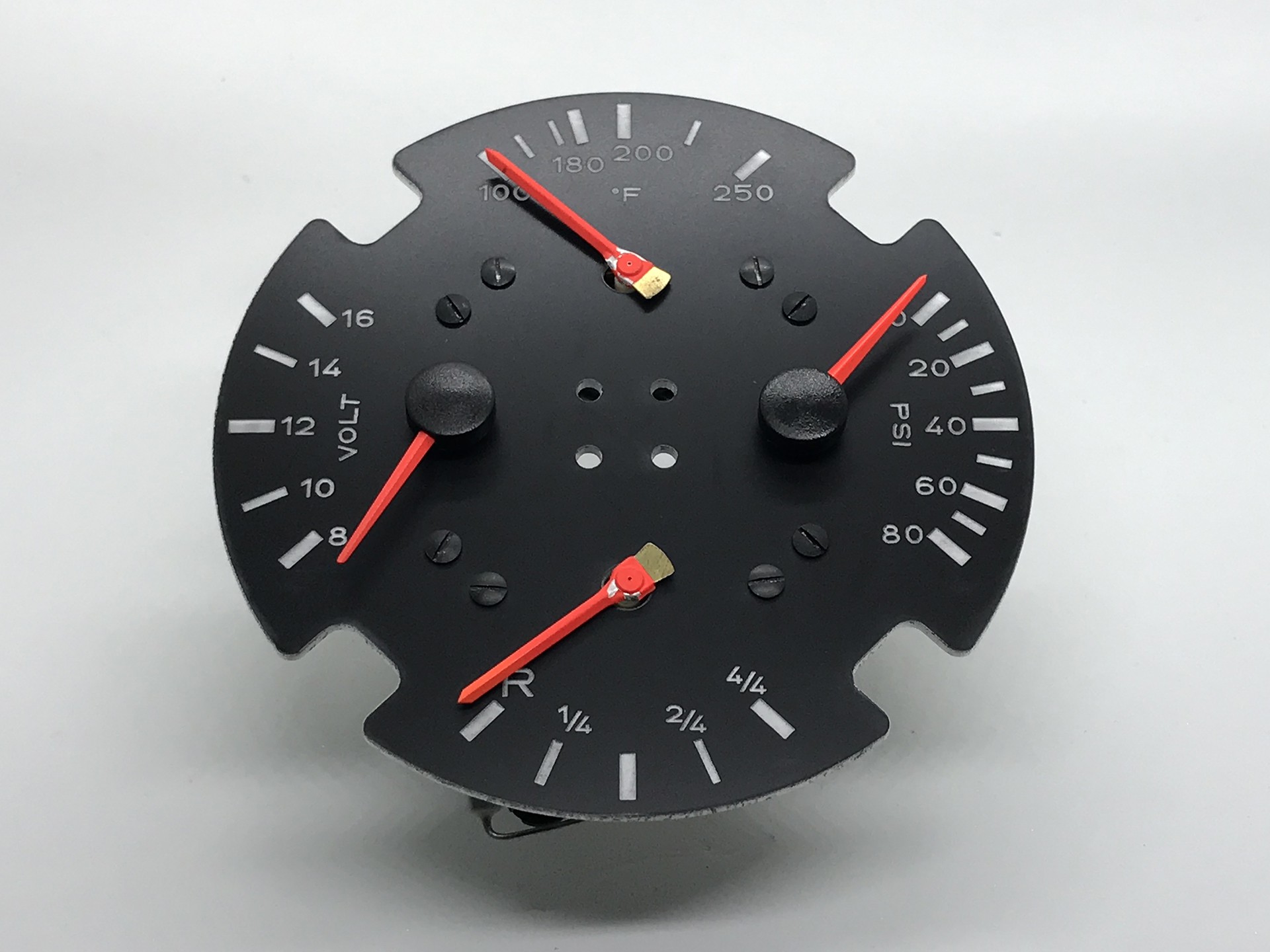
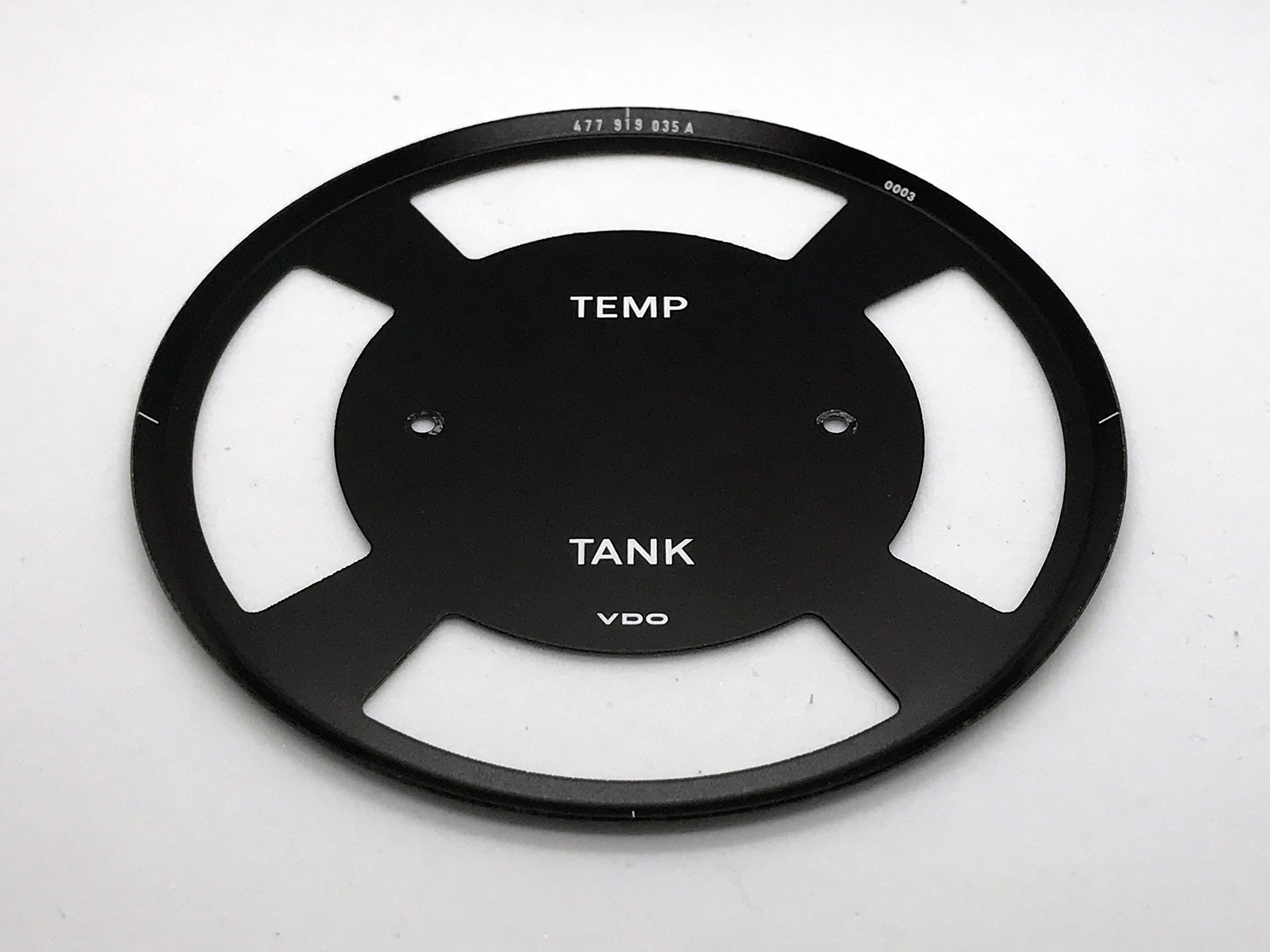
The gauge panel was laser cut and etched from painted acrylic. The final result looks excellent. The VDO gauges were attached to the gauge panel with the factory screws.
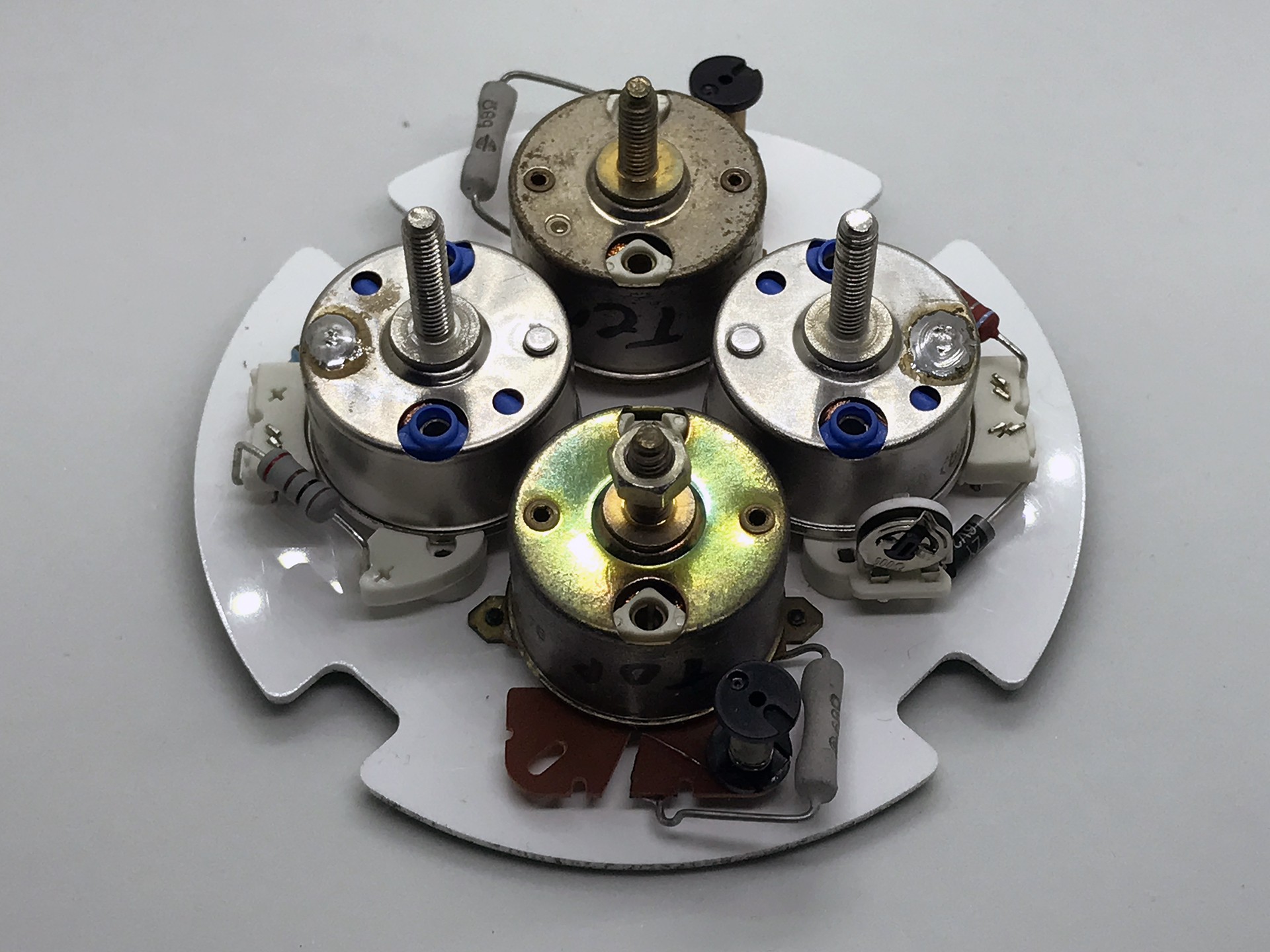
The gauges are packed in as tight as possible and it is obvious which gauges are new and which were salvaged.
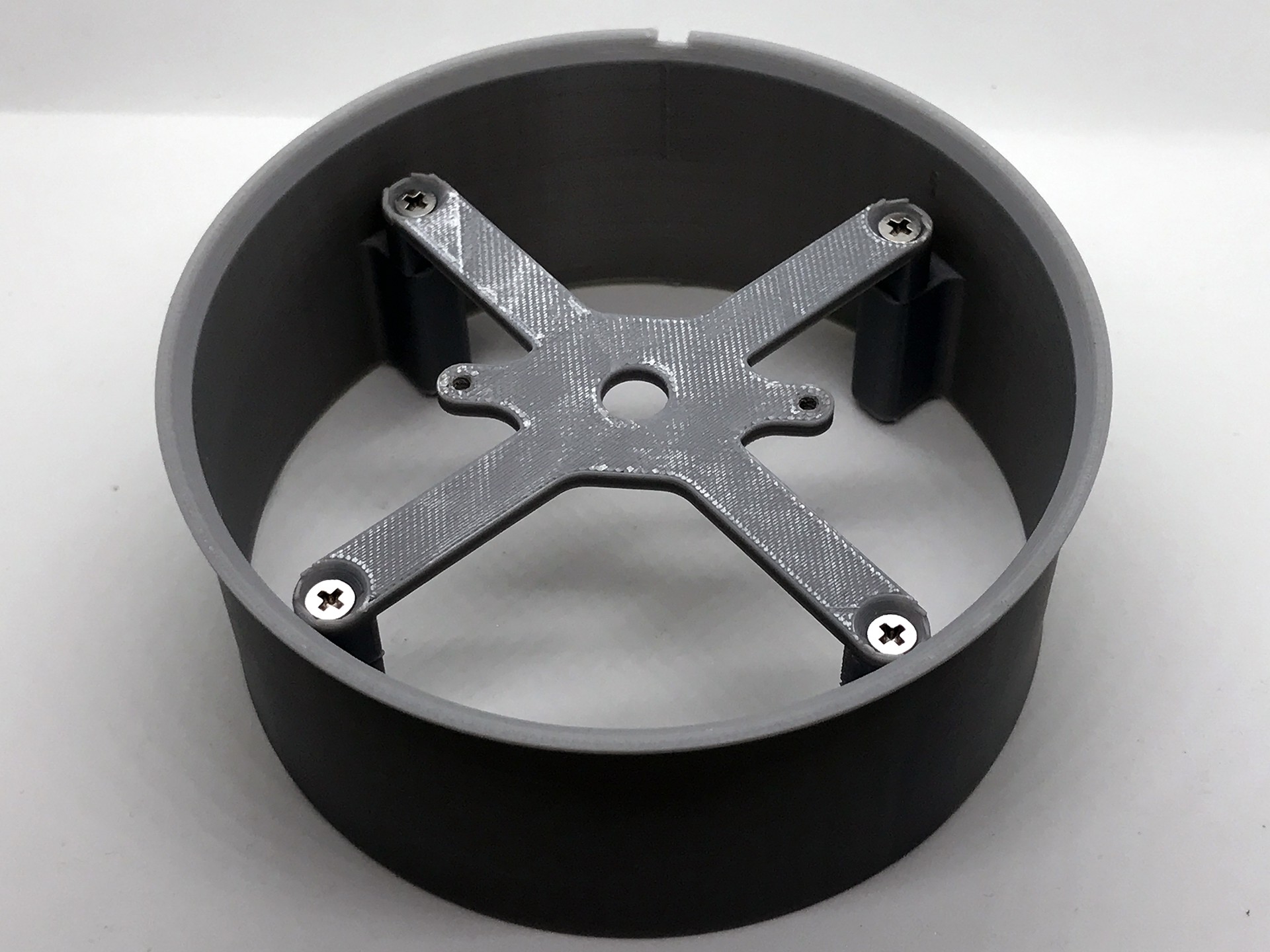
The gauge assembly was mounted on the PCB.
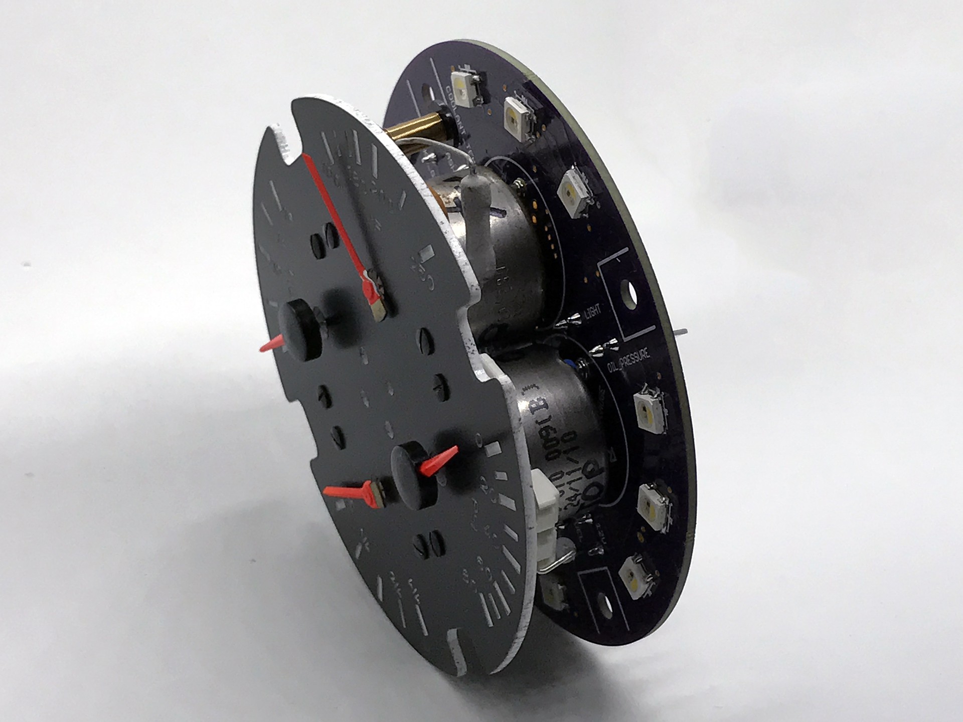
The spacing between the gauge panel and the walls of the enclosure allow light from the LEDs to shine through.
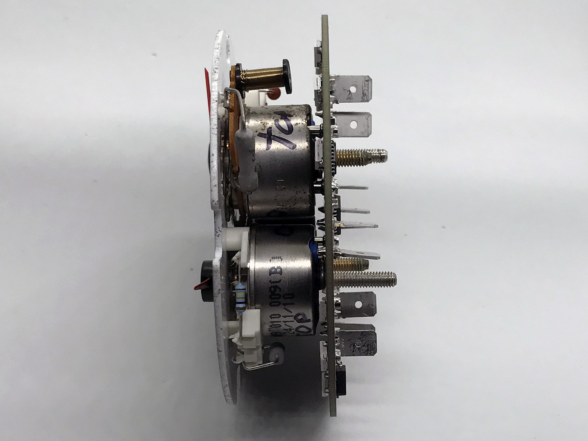
The gauges are secured to the PCB with hex nuts that perform dual functions of securing the gauge and connecting the gauge to ground.
This was the critical piece salvaged from the 944 fuel gauge.
In order to mount the button on the gauge to match my existing gauges, a 7.5mm hole needed to be drilled. Drilling thin sheet metal without damaging the surface is challenging and this jig makes the task much easier.
There are two upper parts of the jig. One with for a 2mm pilot drill and a 7.5mm for the final hole.

The hole was drilled and the button installed without a scratch on the surface.
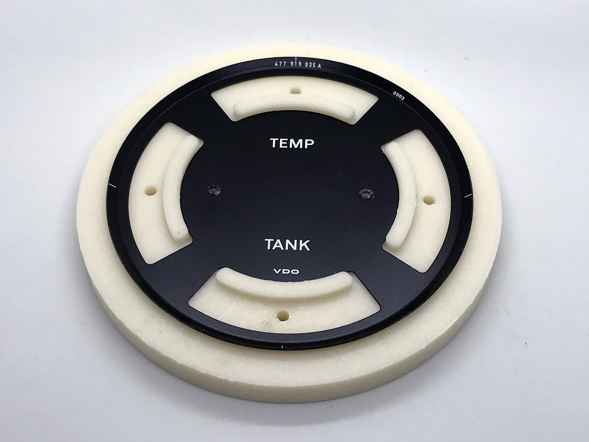
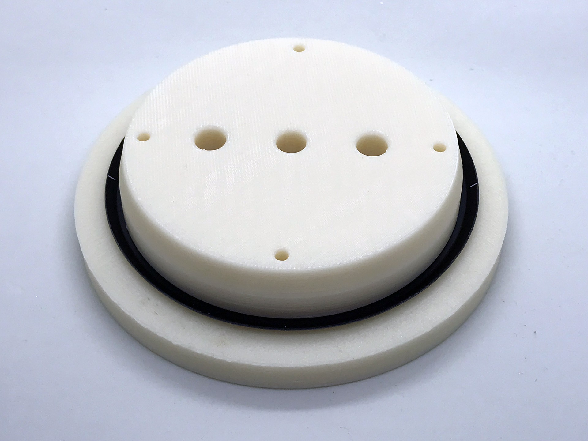
The gauge body is made from 3D printed High Impact Polystyrene. A support inside provides rigidity and a place to mount the gauge face.
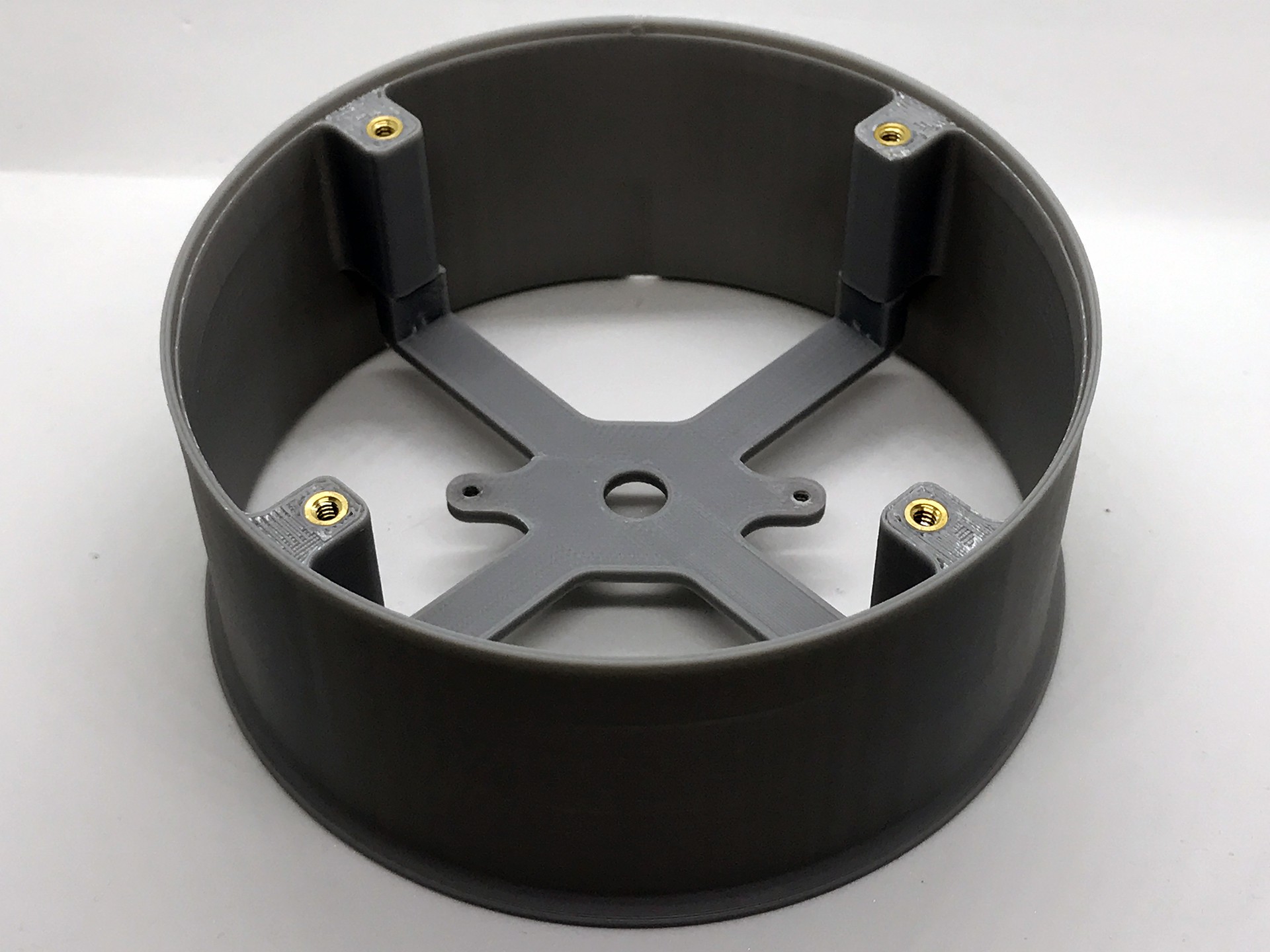
Heat set inserts are used to provide mounting points for the PCB.
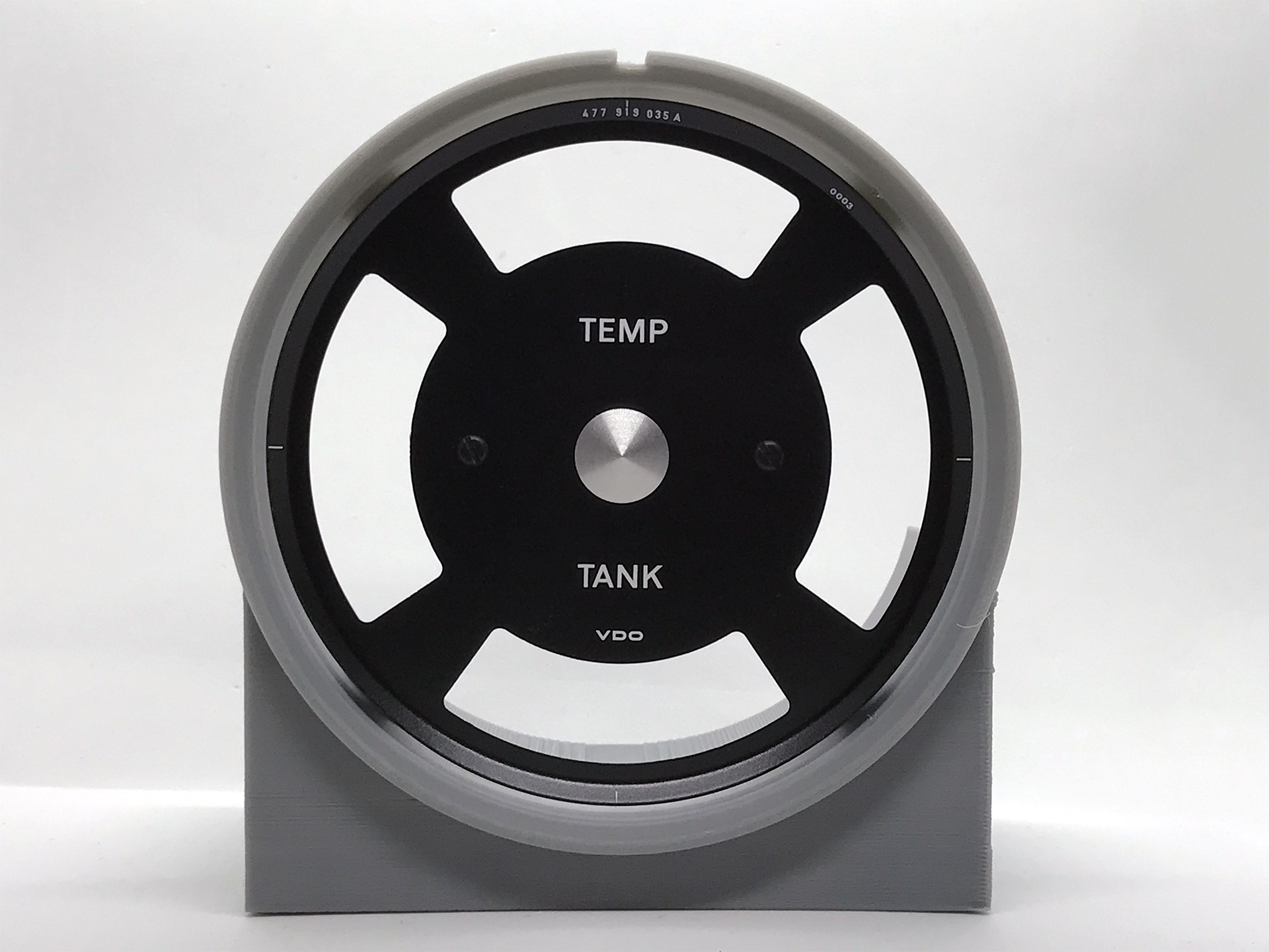
The original two screws from the 944 were trimmed down to 4mm of length and used to attach the gauge face.
The button is secured with hot glue, which is reversible, if it ever needs to be removed.

The front face glass and button from a 914 combo gauge were used to complete the gauge face.
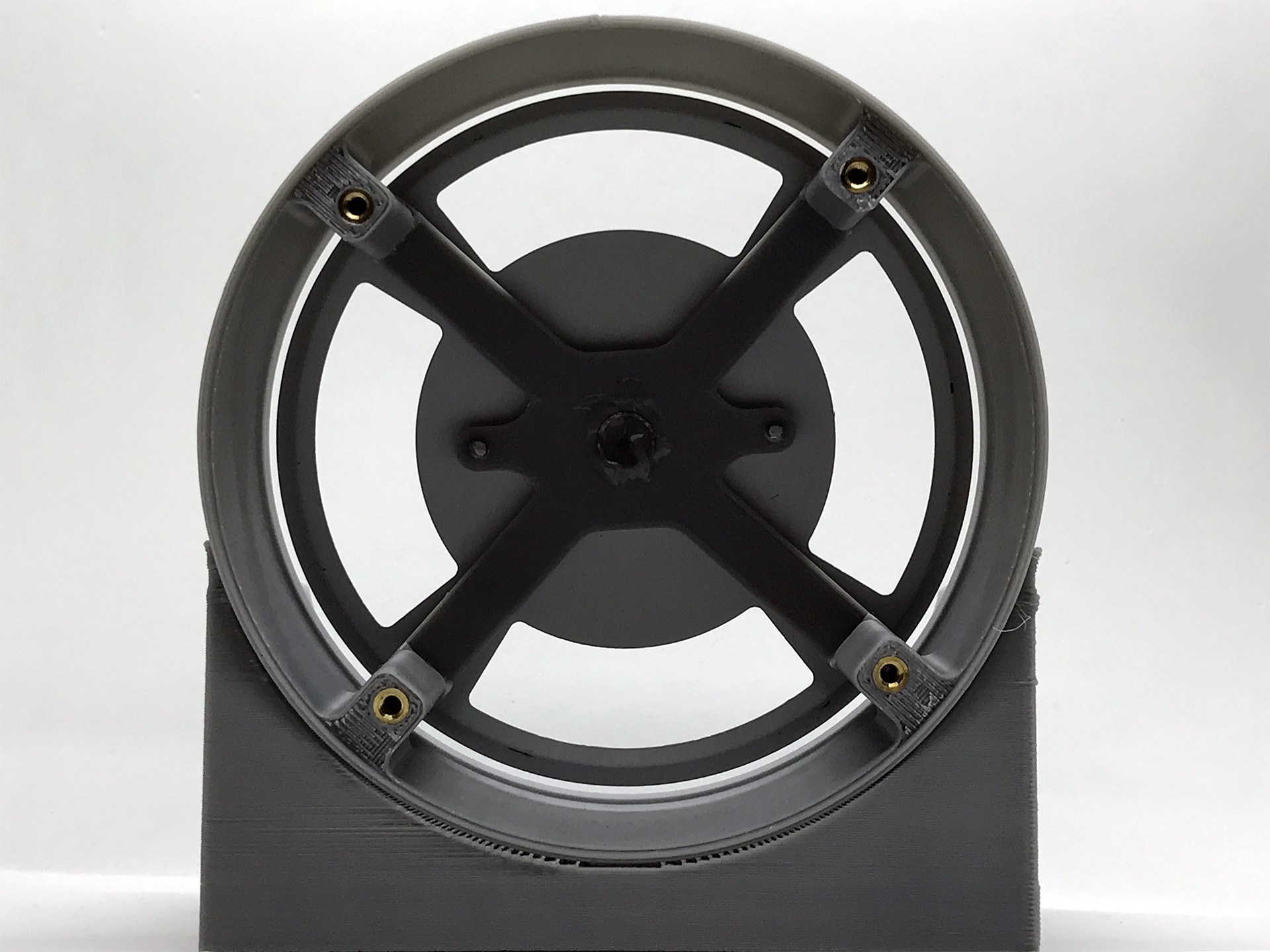
A few taps around the back bends the metal on to the lip of the gauge body. The internals are inserted from the rear, which allows for easy maintenance or firmware changes.

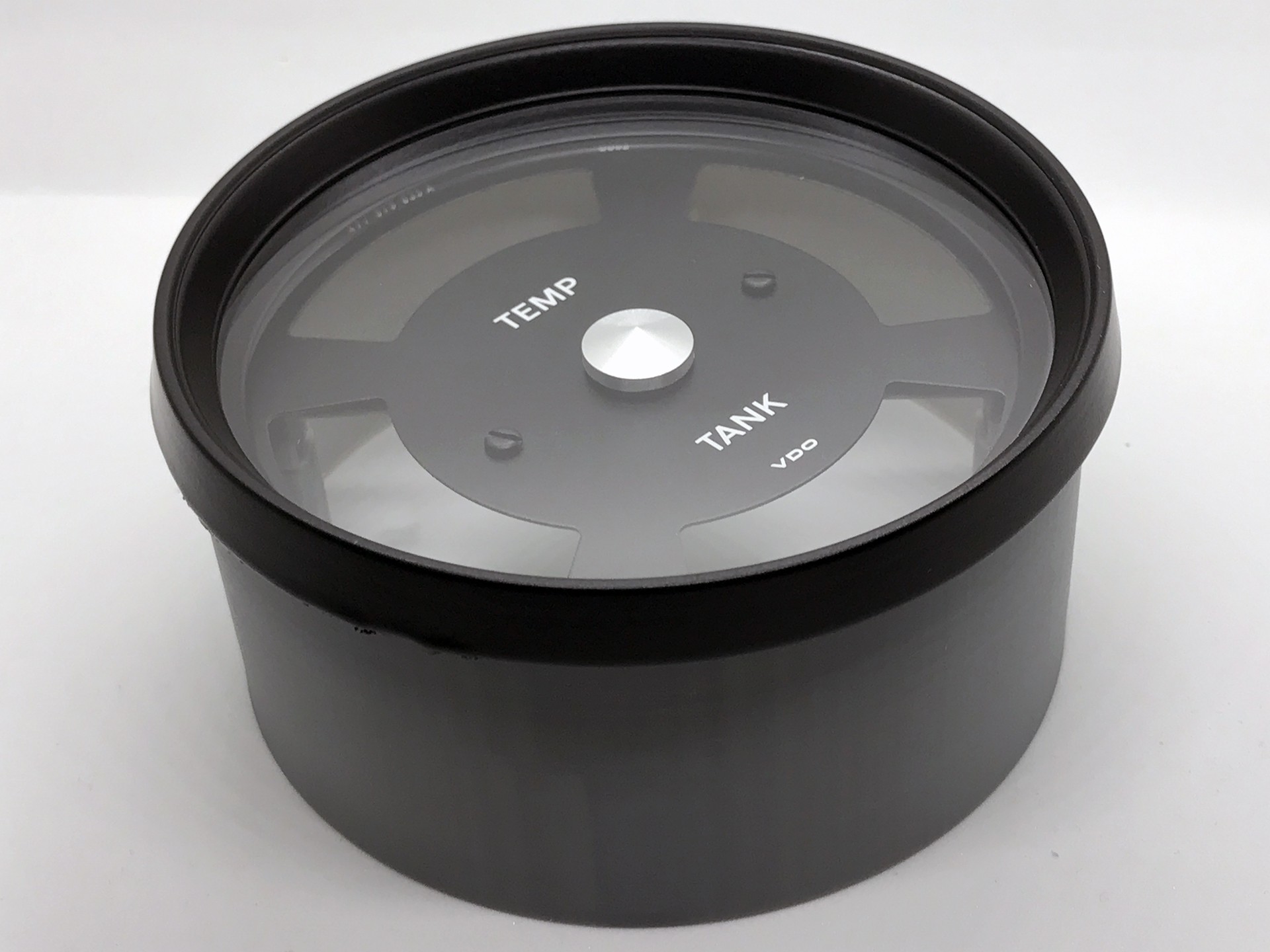
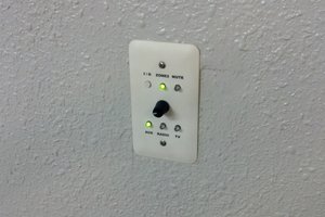
The completed gauge was difficult to photograph as the glass was highly reflective making the markings hard to see.
The PCB provides pogo pin programming port to allow for quick firmware changes. The serial port on the microcontroller was also broken out, but was not populated in this version. The total cost of the project was around $240. The price will vary as the price of 944 and 914 gauges on eBay seem to fluctuate.
The completed gauge in action looks quite good. This iteration of the design is suitable for very low volume production, but the reliance on salvaged parts complicates the process.
I've open sourced the design and it's available in this Github repo.


 mulcmu
 Stephen Harrison
 Quinn
Quinn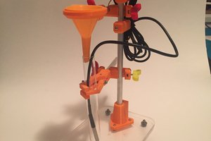
 Tinkers Projects
Brilliant, Really nice result, I was going to look into doing similar for my T25 but less sophisticated than this. The only thing I would say though is the fuel gauge is labelled wrong, Should be 1/4 2/4 3/4 4/4