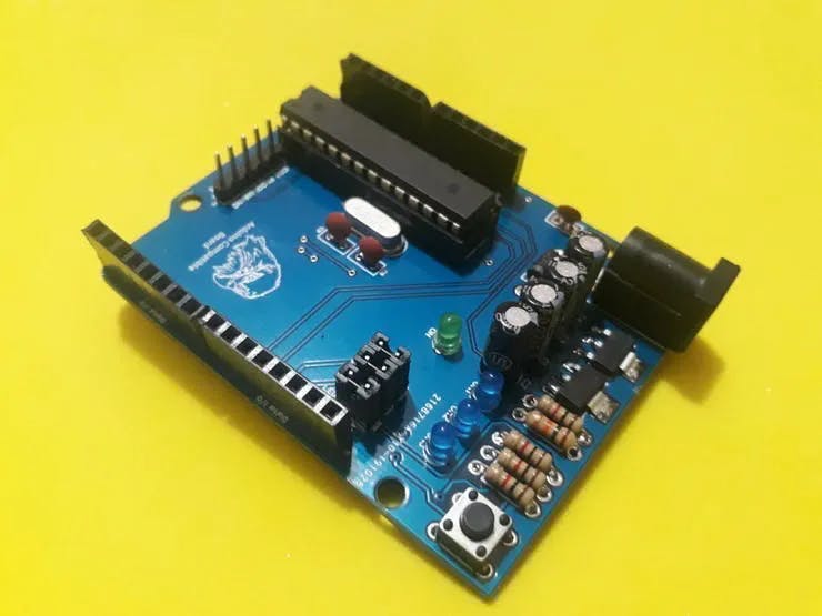
For this project, we'll use the JLCPCB Arduino Compatible printed circuit board presented below.
You can obtain the Arduino JLCPCB compatible PCB for your projects for $2 in your first order with the link: Earn my PCBs Arduino Compatible.
Use the JLC-RECE coupon, earn a $2 off discount, and earn 5 PCBs.
Read the first part of this article!
Now, we'll start the project.
This is the second article that gives us a series of how to build a fake pump as an Arduino Uno and an HC 12 radio transceiver.
In this article, we will develop a bomb receiver that will consist of LEDs, and a buzzer to indicate three situations:
- 1st Situation: Pump activated - Yellow led on
- 2nd Situation: Pump off - Green led access
- 3rd Situation: Bomb exploded - Red led and buzzer activated
So in this article, we will develop the fake pump receiver with Arduino and you will learn the following points:
- Perform the circuit assembly on the protoboard
- Understand how the HC 12 module works
- Perform the Arduino communication with the HC 12 module
- Remote actuation of actuators
- Writing the counting time on the I2C LCD display
Now, we will start the full presentation of the development of the fake pump receiver project with Arduino Uno.
DEVELOPING THE FAKE PUMP RECEIVER PROJECT WITH ARDUINO UNO
As previously mentioned, the project consists of creating the fake pump receiver with Arduino Uno.
The HC 12 module is a radio transceiver and its operating frequency is 433.4 MHz to 473 MHz.
It is possible to connect two types of antennas in this module, a helical antenna that comes with the module or another antenna to be connected to the UFL connector.
These modules usually come with some factory settings, so that we can communicate 2 HC 12 modules with an Arduino Uno, Nano we need to adjust some parameters like communication speed, communication channel, operation mode using AT commands.
To configure the module, the set pin must be connected to the GND according to figure 1 for the module to enter configuration mode.
It is recommended to supply the HC 12 module with an external 5 V source, as it has some serial USB converters that do not provide enough current to supply the module.
The GND of the USB serial converter must be connected to the GND of the power supply.

Figure 1 - Schematic circuit with the serial converter connections to the HC 12 module.
Now let's go to the list of components needed to assemble the circuit in Figure 1 to perform the configuration of the HC 12 module.
To configure the module, we will use the Termite software.
Termite Software is software that allows commands to be sent to the HC 12 module.
The Arduino IDE's serial monitor could also be used.
Let's go to the HC 12 module settings.
Table 1 shows the main commands used to configure the module using AT commands.


The FU1 and FU2 modes have lower power consumption than the FU3 mode, so the FU1 and FU2 modes are modes to be used in applications that use batteries.
The FU1 mode operates with an electric working current without transmitting 3.6 mA data.
The FU2 mode, on the other hand, operates with a working current of 80uA without transmitting data and supports only the speeds 1200 bps, 2400 bps, 4800 bps.
The operating modes are not compatible with each other, so the two modules must be configured in the same operating mode, whether FU1, FU2, FU3.
Before starting the module configuration, we must download the Termite software available at the link https://termite.software.informer.com/download/#downloading
After making the connections with the HC 12 module and the serial USB converter, open the Termite softwareConfiguring the HC 12 module with Termite software.
Configuring the HC 12 module with Termite software.

After opening the Termite software, we must click on Settings to make some settings according to the Figure below.

After making the settings in the Termite software, click Ok and then COM3 to connect the USB - serial converter with the HC 12 module to the serial port that is connected.
It is expected to connect the port with the Termite software and we type the AT command in the command bar.
If all goes well, OK will appear as in figure 4.

After this initial test we will configure the HC 12 module with the following parameters:
- Serial communication speed: 9600 bps;
- Communication channel 5;
- 11 dBm transmission power;
- Operating mode FU3.


After configuring the HC 12 module, we will program the Arduino.
After configuring the module, we can connect to the Arduino as shown in figure 8 for the transmitter (Pump).
The Arduino Uno will be the pump's receiver, the receiver will have the LEDs and the buzzer, in addition to the HC 12 radio transceiver.

In Arduino Uno, there are 3 LEDs and a buzzer.
- Yellow LED - Pump activated and counting started
- Green led - Pump deactivated
- Red led and buzzer activated - Bomb exploded.
Now, let's explain the connections of the HC-12 module on the Arduino Uno.
The Tx pin of the HC 12 module is connected to the digital pin 8 of the Arduino and the RX pin of the HC 12 module is connected to the digital pin 7 of the Arduino Uno.
We will use a library called Serial Software to configure these pins 7 and 8 as serial communication pins, that is, we will emulate serial communication by software.
After assembling the pump receiver circuits we will program it.
Receiver Code Development
First, we included the Serial Software library, a library responsible for emulating any ATMega 328P microcontroller pin as a serial communication pin.
#include <SoftwareSerial.h>
Sets pins 8 and 7 as RX and TX.
SoftwareSerial HC12(8,7); // RX , TX
Name pins 6, 10 and 11 with the name of the actuators that are connected to them.
#define buzzer 6#define verde 10#define amarelo 9#define vermelho 11
Char variable that stores the content coming from the HC 12 module serial.
char comando;
Pin configuration function as outputs and serial communication speed of the HC 12 module and the uC Serial only for system testing.
void setup(){pinMode(buzzer,OUTPUT);pinMode(verde,OUTPUT);pinMode(amarelo,OUTPUT);pinMode(vermelho,OUTPUT);HC12.begin(9600);digitalWrite(buzzer,1);digitalWrite(amarelo,1);digitalWrite(verde,1);digitalWrite(vermelho,1);delay(300);digitalWrite(buzzer,0);digitalWrite(amarelo,0);digitalWrite(verde,0);digitalWrite(vermelho,0);delay(300);Serial.begin(9600);}
The void loop function is where the main logic of our project.
void loop(){
While receiving data it stays within that while.
While receiving data it stays within that while.
The comando variable stores the content that comes through the HC12 module.
comando = HC12.read();Serial.println(comando); // Escreve o que vem da serial do HC12
Decision structure based on the variable command
- If it receives L, the yellow led is activated, it means that the pump has been activated;
- If you receive d the green led is activated, it means that the pump has been deactivated and the other LEDs and buzzer are deactivated;
- If it receives E the bomb exploded and the red led and the buzzer are activated;
- If it receives 0, the LEDs and the buzzer are deactivated.
switch(comando){case 'L' : digitalWrite(amarelo,1);digitalWrite(buzzer,0);digitalWrite(verde,0);digitalWrite(vermelho,0);break;case 'D' : digitalWrite(amarelo,0);digitalWrite(buzzer,0);digitalWrite(verde,1);digitalWrite(vermelho,0);break;case 'E' : digitalWrite(amarelo,0);digitalWrite(buzzer,1);digitalWrite(verde,0);digitalWrite(vermelho,1);break;case '0' : digitalWrite(amarelo,0);digitalWrite(buzzer,0);digitalWrite(verde,0);digitalWrite(vermelho,0);break;}}}
Now, let's see the result of the code with the electronic circuit.
Results
After programming the Arduino you can check the results below. When the pump is activated, the orange LED is on on the receiving device. This can be seen in the figure below.

When the pump is deactivated by the police team, the green LED is activated on the receiving device.

Finally, we have the Red LED activated. It is activated when the bomb explodes.

Now it's your turn to put this project together and have fun with your friends in paintball or airsoft.
Read the first part of this article!
Conclusion
In this article we learned how to develop the fake pump receiver using an Arduino Uno, HC 12 leds transceiver and buzzer.
Now we have the complete fake pump and receiver system, good fun.
As a suggestion, you can place the circuit in a Patola box and develop a customized board using the Arduino Uno or Atmega 328P microcontroller for this project, avoiding using the Arduino board. For this project, we'll use the JLCPCB Arduino Compatible printed circuit board presented below.
You can obtain the Arduino JLCPCB compatible PCB for your projects for $2 in your first order with the link: Earn my PCBs Arduino Compatible.
Use the JLC-RECE coupon, earn a $2 off discount, and earn 5 PCBs.