For this project, we'll use the JLCPCB Arduino Compatible printed circuit board presented below.
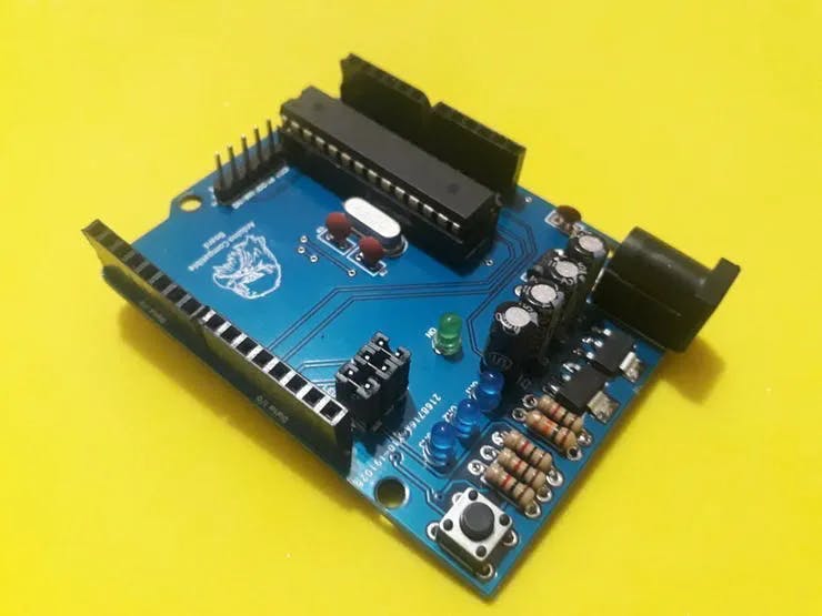
Figure 7 - Arduino Standalone Printed Circuit Board to control the Arduino Line follower Robot.
You can obtain the Arduino JLCPCB compatible PCB for your projects for $2 in your first order with the link: Earn my PCBs Arduino Compatible.
Use the JLC-RECE coupon, earn a $2 off discount, and earn 5 PCBs.
Read the second part of this article.
Now, we'll start the project.
Airsoft is a sports game where players participate in simulations of police, military, or mere recreation with pressure weapons that shoot non-lethal plastic projectiles, often using military tactics.
It is practiced indoors or outdoors. AirSoft guns can be purchased at various online or physical stores. Have you thought about building your fake bomb for Air Soft competition using an Arduino and a radio transceiver?
This article will be divided into two parts: The first will be the pump itself, which will be the transmitter. In this pump it will be possible to configure the activation time, as well as to activate or deactivate it by means of buttons.
And the second part of the article will be the receiver that will contain the LEDs that will be activated according to the three possible conditions:
- 1st Bomb activated: The transmitter sends the L to the receiver and the yellow LED is on. Button B3 activates the pump.
- 2nd Bomb deactivated: The transmitter sends the D to the receiver and the yellow LED is turned off and the green LED is lit indicating a safe situation. Button B4 is responsible for deactivating the pump if the configured time has not elapsed.
- 3rd Bomb exploded - After the time has elapsed, the bomb is activated (Red LED and buzzer are activated).
Therefore, in this article, we will develop a fake bomb with Arduino and you will learn:
- Perform the assembly of the circuit in the protoboard;
- Understand the operation of the HC 12 module;
- Perform the communication of the Arduino with the HC 12 module;
- Reading digital inputs;
- Writing the counting time on the I2C LCD display.
Now, we will start the full presentation of the development of the fake bomb project with Arduino Uno.
Developing the Fake Bomb Project With Arduino UNO
As previously mentioned, the project consists of creating a fake bomb with Arduino Uno. The HC 12 module is a radio transceiver and its operating frequency is From 433.4 MHz to 473 MHz.
It is possible to connect two types of antennas in this module, a helical antenna that comes with the module or another antenna to be connected to the UFL connector.
These modules usually come with some factory settings, so that we can communicate 2 HC 12 modules with an Arduino Uno, Nano we need to adjust some parameters like communication speed, communication channel, operation mode using AT commands.
To configure the module, the set pin must be connected to the GND according to figure 1 for the module to enter configuration mode.
It is recommended to supply the HC 12 module with an external 5 V source, as it has some serial USB converters that do not provide enough current to supply the module.
The GND of the USB serial converter must be connected to the GND of the power supply.

Figure 1 - Schematic circuit with the serial converter connections to the HC 12 module.
Now let's go to the list of components needed to assemble the circuit in Figure 1 to perform the configuration of the HC 12 module.
Next, we will learn how to configure the HC-12 module with Termite Software.
HC-12 Module configuration process
To configure the module, we will use the Termite software. Termite Software is software that allows commands to be sent to the HC 12 module. The Arduino IDE's serial monitor could also be used.
Let's go to the HC 12 module settings. Table 1 shows the main commands used to configure the module using AT commands.


Table 1 - Data to configurate the HC12 Module.
Configuring the HC 12 module with Termite software.

Figure 3 - Termine Software.
After opening the Termite software, we must click on Settings to make some settings according to Figure 3.
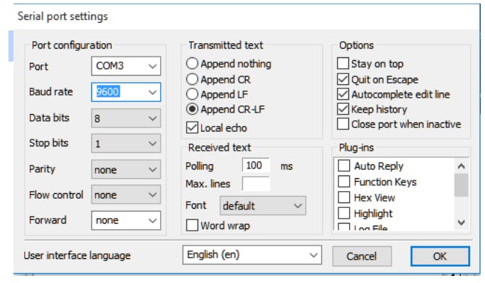
Figure 3 - Termite software settings.
After making the settings in the Termite software, click Ok and then COM3 to connect the USB - serial converter with the HC 12 module to the serial port that is connected.
It is expected to connect the port with the Termite software and we type the AT command in the command bar.
If all goes well, OK will appear as in figure 4.

After this initial test we will configure the HC 12 module with the following parameters:
- Serial communication speed: 9600 bps;
- Communication channel 5;
- 11 dBm transmission power;
- Operating mode FU3.
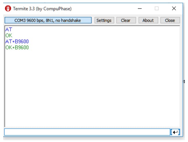
Figure 5 - Termite software configuring the communication speed of the HC 12 module.

Figure 6 - Termite software configuring the communication channel and transmission power.
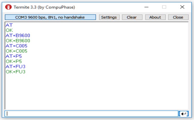
Figure 7 - Termite software configuring the operation mode of the HC 12 module.
After configuring the HC 12 module, we will program the Arduino.
After configuring the modules, we can connect to the Arduino as shown in figure 8 for the transmitter (bomb).
The Arduino Uno will be the pump (transmitter), in the bomb, it will be possible to configure the bomb activation time through buttons, as well as to activate and deactivate the bomb.
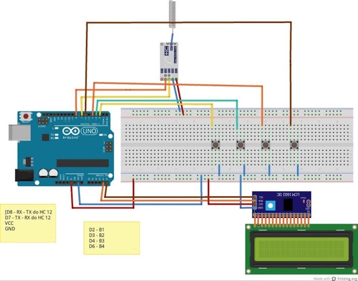
Figure 8 - Arduino Uno bomb circuit
In Arduino Uno, we will use 4 buttons for setting the activation time and activation or deactivation of the pump.
- B1 - Adjusts pump activation time varying from 4 minutes to 10 minutes.
- B2 - Turn off the bomb after it has exploded.
- B3 - Activates the pump, sends the L character to the receiver and turns on the yellow LED of the same.
- B4 - Disables the pump as long as the activation time has not been exhausted.
All buttons are activated at a low logic level (0V).
Next, we will present the code of the pump's transmitting circuit.
First, we include the LiquidCrystal_I2C libraries, which is the library responsible for using the LCD display.
#include <LiquidCrystal_I2C.h>
Then we included the Serial Software library, the library responsible for emulating any pin of the ATMega 328P microcontroller as a serial communication pin.
#include <SoftwareSerial.h>SoftwareSerial HC12 (8,7);// RX, TX // Configura os pinos 8 e 7 como pinos RX e TX decomunicação serialLiquidCrystal_I2C lcd (0x27,2,1,0,4,5,6,7,3,POSITIVE); // Configuração do endereço e pinos do display lcd I2CHardware mapping on pins B1, B2, B3 and B4// Mapeamento de Hardware#define B1 2#define B2 3#define B3 4#define B4 6// Declaração de variaveis globaisunsigned long tempo =0; // Variable to store current timeboolean en =0,ex =0; //Boolean variables to store the count enable at = 1 and when the bomb explodes ex = 1int minutos =4, seg=0; //Variable to store minutes and seconds
Next, we have the function of configuring the pins with input, serial communication of the HC 12, and initialization of the 16 x 2 display.
void setup(){HC12.begin(9600);lcd.begin(16,2);pinMode(B1,INPUT_PULLUP); // Configuramos o pino como entrada e ativamos o resistor de Pull up interno com o commando INPUT_PULLUPpinMode(B2,INPUT_PULLUP);pinMode(B3,INPUT_PULLUP);pinMode(B4,INPUT_PULLUP);Serial.begin(9600);lcd.setCursor(0,0);lcd.print("BOMBA AIR SOFT" );}
Finally, we have the void loop function. It presents all the operating logic of the bomb design.
void loop(){If B1 is pressedif(!digitalRead(B1))// If B1 is pressed it increases the minutes, it is possible to adjust the time from 4 to 10 minutes{lcd.setBacklight(HIGH);lcd.clear();lcd.setCursor(0,0);lcd.print("BOMBA AIR SOFT" );minutos+=1;if(minutos>10) //If minutes is greater than 10 it returns to the value 4{minutos =4;}
Write the time on the display.
lcd.setCursor(0,1);lcd.print("Tempo " );lcd.setCursor(6,1);lcd.print(minutos );lcd.setCursor(8,1);lcd.print(":" );lcd.setCursor(10,1);lcd.print(seg );while(digitalRead(B1)==0);}
If B2 is pressed, the bomb is turned off after it explodes and returns to the initial display screen.
if(!digitalRead(B2)) //B2 turns off the pump and returns the time to 4 minutes, so you don't have to press the reset{seg =0;minutos =4;ex=0;HC12.print('0'); // Envia 0 para o receptorlcd.setBacklight(HIGH);lcd.clear();lcd.setCursor(0,0); // Linha 0, coluna 0lcd.print("BOMBA AIR SOFT" );while(digitalRead(B2)==0);}
If B3 is pressed, it enables counting and writes messages on the display, sends L to the receiver.
if(!digitalRead(B3)){en =1;lcd.clear();lcd.setCursor(0,0);lcd.print("Bomba ativada" );HC12.print('L'); //Bomba ativadawhile(digitalRead(B3)==0);}
If B4 is pressed and the bomb has not yet exploded, the bomb is deactivated.
if(!digitalRead(B4)&& ex ==0){HC12.print('D'); // Envia D para o receptor- Bomba desativadaen =0;lcd.clear();lcd.setCursor(0,0);lcd.print("Bomba desativada" );lcd.setCursor(0,1);lcd.print("Tempo " );lcd.setCursor(6,1);lcd.print(minutos );lcd.setCursor(8,1);lcd.print(":" );lcd.setCursor(10,1);lcd.print(seg );while(digitalRead(B4)==0);}
With en = 1 the count is started, and the time variable stores the millis value, and every 1 second the seconds are decremented if sec > 0.
if(en ==1 ){if(millis() - tempo >=1000)// Intervalo para decremento do tempo{tempo = millis();lcd.clear();if(seg >0) // Se segundos for maior que 0 decrementa a variável seg{seg-=1;}
If minutes are different from 0 and seconds are less than or equal to 0, increments - 1 of minutes and seconds is equal to 59.
if(minutos !=0 && seg <=0) //Decreases minutes if different from 0 and seconds is less than 0{minutos-=1;seg =59;//if(minutos<=0){minutos =0;}}
Messages were written on the LCD display.
lcd.setCursor(0,0);lcd.print("Activated Bomb!" );lcd.setCursor(0,1);lcd.print("Time " );lcd.setCursor(6,1);lcd.print(Minutes );lcd.setCursor(8,1);lcd.print(":" );lcd.setCursor(10,1);lcd.print(seg );}
If minutes equals 0 and seconds = 0 the time has elapsed, then ex = 1.
if(minutos ==0 && seg ==0) //If minutes equals 0 and seconds equals 0 the bomb explodes{ex =1;}}if (ex ==1) //If ex = 1 means that the time has elapsed and the bomb explodes, send E to the receiver and write the message on the display.{lcd.setCursor(0,0);lcd.print("Airsfot Bomb");en =0;lcd.setCursor(0,1);lcd.print("Exploded !!! " );HC12.print('E'); //Bomb exploded}}
Now, we will see the result of the implemented code.
Fake Bomb circuit operation
After programming the Arduino you can check the results below:

Figure 9 - Physical assembly of the fake pump
After pressing B1 the pump activation time is activated.

Figure 10 - Bomb activated and counting started.
If B4 is pressed, the pump is deactivated.

Figure 11 - Pump deactivated.
If B4 is not pressed, counting continues until the bomb explodes.

Figure 12 - Bomb exploded.
Finally, we reached the end of our project and developed the fake bomb transmitter part with Arduino.
Conclusion
In this article, we learned how to develop a fake bomb using an Arduino Uno, HC 12 transceiver, and an LCD display.
In our next tutorial, we will develop the receiver that will be activated according to the conditions mentioned at the beginning of the article.
Read the second part of this article now!
Acknowledgments
We thank the company JLCPCB - Printed Circuit Board Factory for the support and partnership in the development of this project.
We thank the Robô Lúdico School in Brazil to create several projects and courses about robotics and Arduino.
We leave a link for you to purchase your printed circuit boards for a value of $ 2 through that link. Use the JLC-RECE coupon,earn a $2 off discount, and earn 5 PCBs.