 Michael Gardi
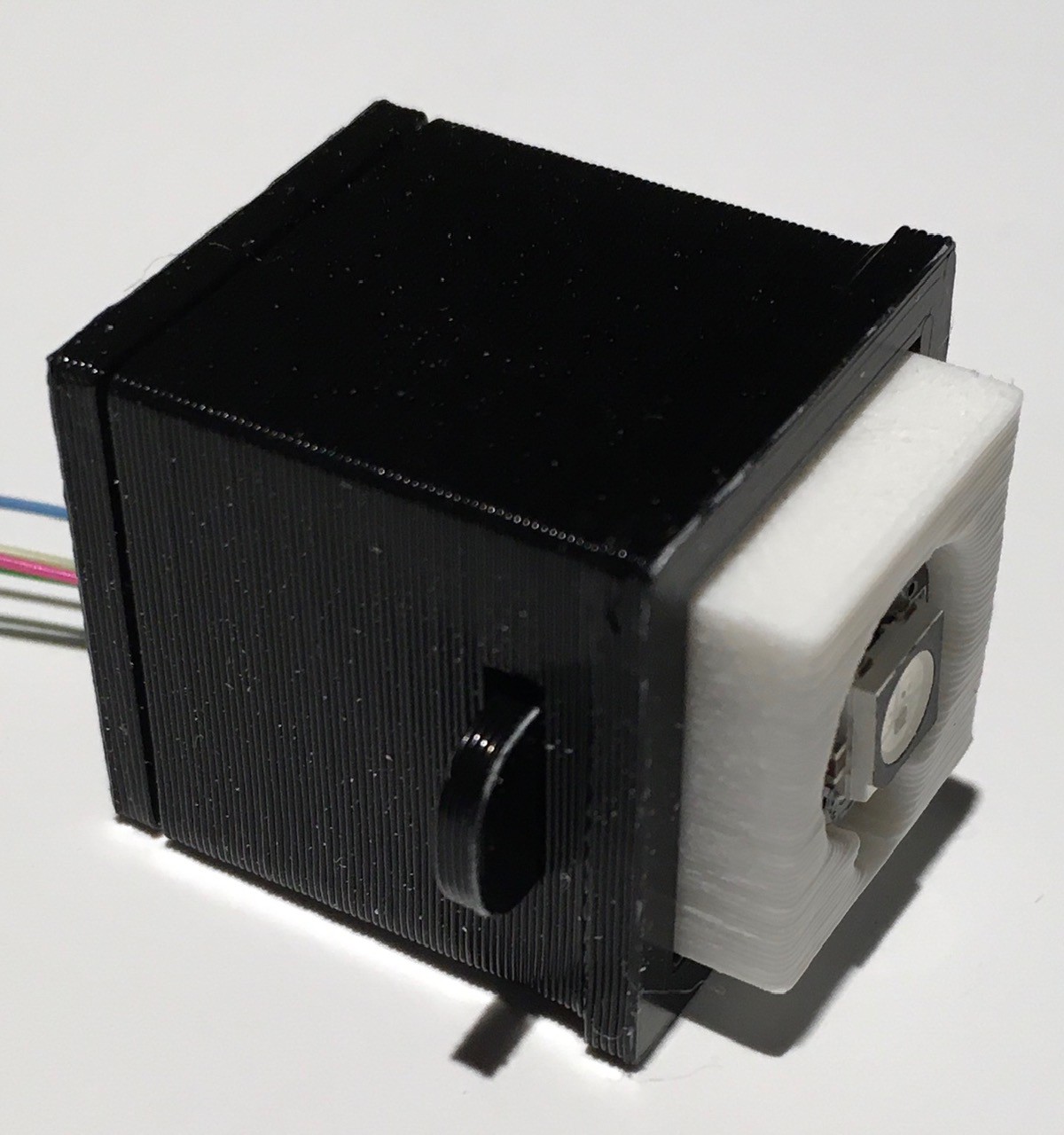
While the rotary switch turned out great, and certainly would have done the job, I think I'm going to go in a different direction for Think-a-Tron 2020. The key to this new concept is a push button. Not just any push button, but an illuminated push button, and not just any illumination, but WS2812B addressable, smart RGB LED pixel light illumination. It looks like this:
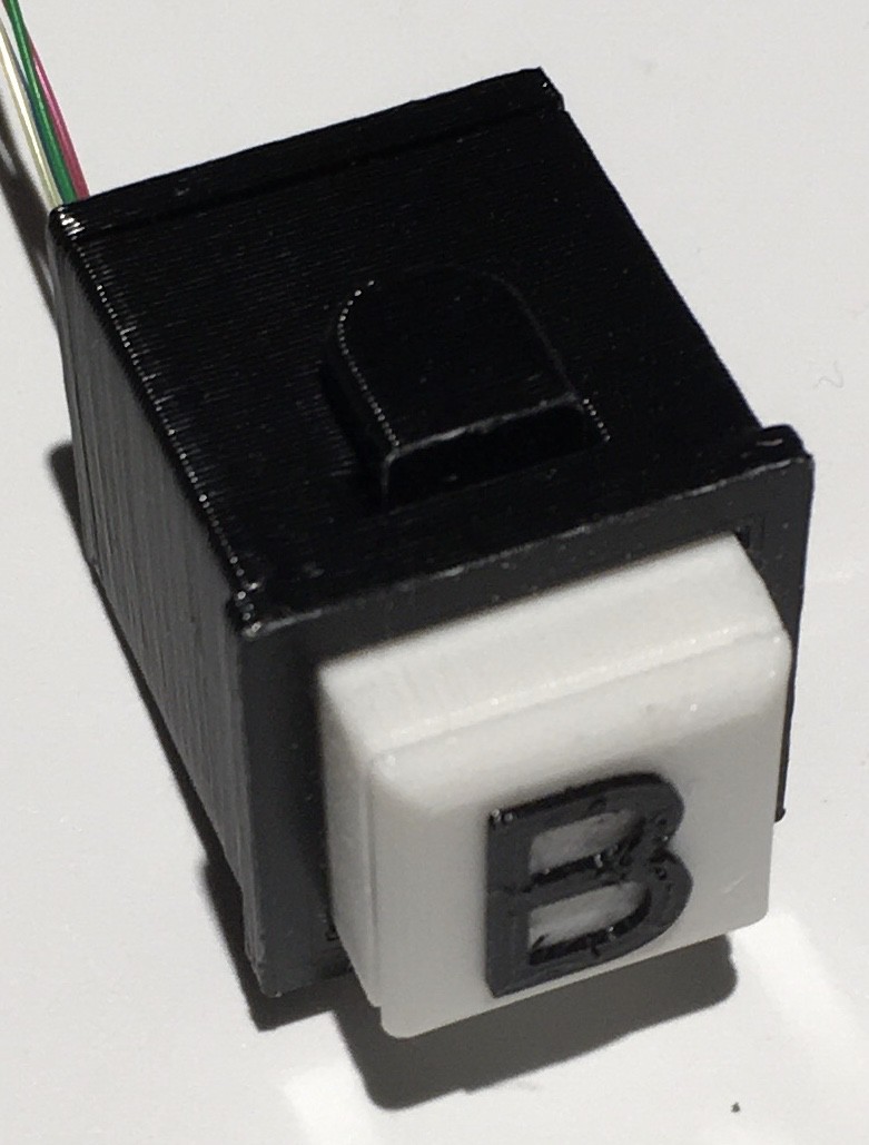
There will be five of these per player, one for each answer choice A, B, C, T, or F. When the player wants to "lock in" their answer, they just have to press the appropriate button, and it will light up. The five will act as radio buttons, so only the last one pressed will ever be the illuminated choice. Since the LEDs can be any color, one can envision changing correct answers to green and incorrect answers to red after Think-a-Tron 2020 has declared the correct choice. There are many blinkenlight possibilities.
To be clear what I have here is a combination of a push button switch and an RGB addressable LED. They are not integrated in the sense that the switch controls the LED in any way, that's all done "centrally".
Building a NeoPixel Push Button
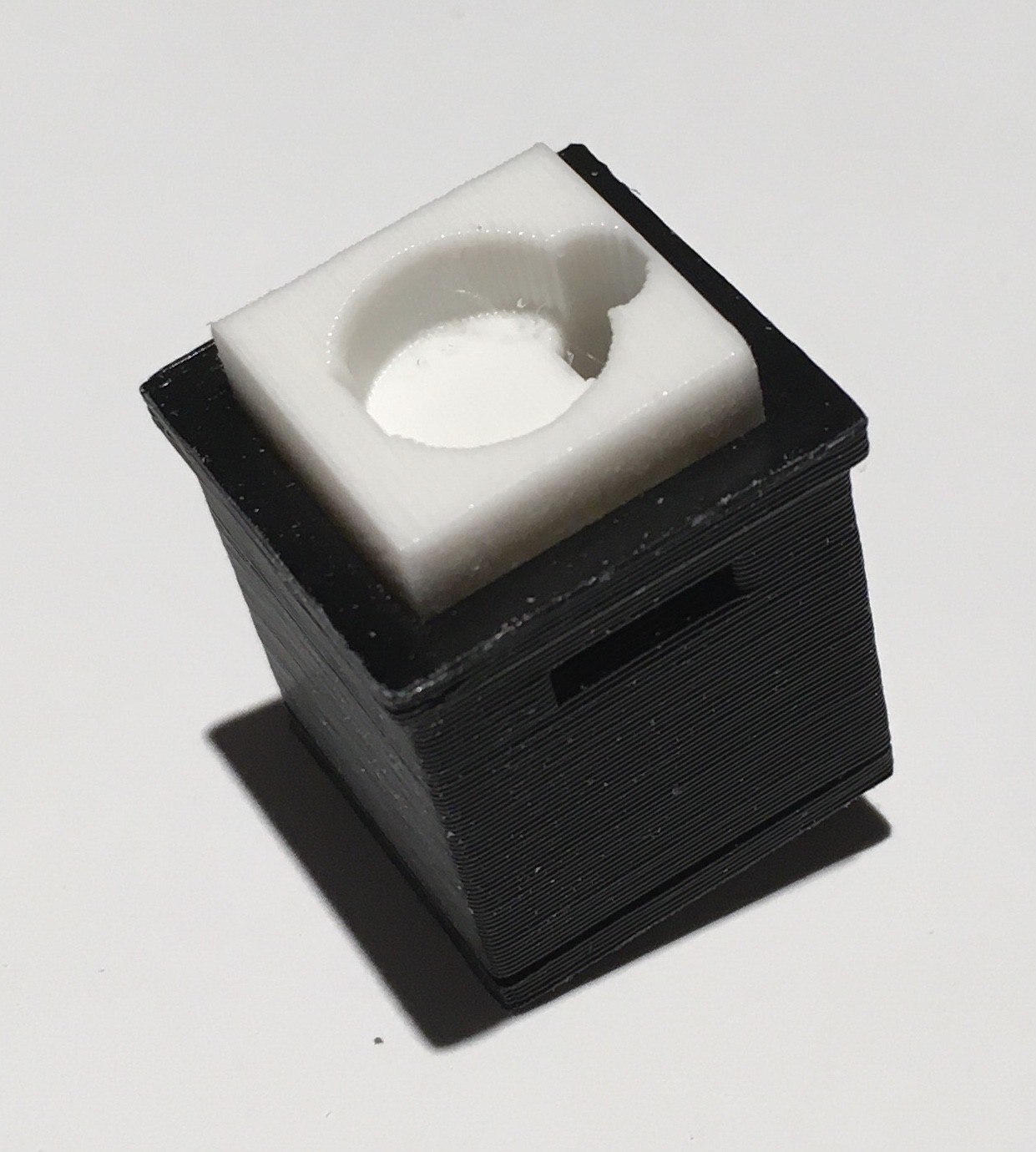
I started with a design that I used in my TMD-1 project for the panel buttons, and incorporated the same smart pixel units that I use for the 5x7 LED array. Here are all the parts you need to make one.
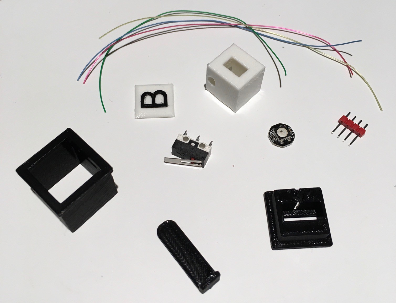
So we are talking about a simple push button switch here that I built around a small micro switch (Amazon: Gikfun Micro Switch Long Hinge Lever (Pack of 20pcs) for Arduino EK1713) that I had lying around.
Assembly is pretty straight forward. Start by sliding the micro switch into the base piece making sure that the lever actuator does not extend past the edge of the base (there is one right and one wrong way to do this).
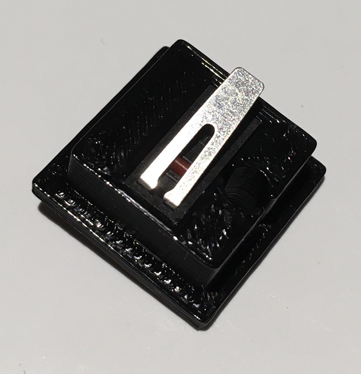
Now attach the base piece to the bottom of the console mounting piece. Mine friction fit pretty good, but you can used a small amount of glue to hold it firmly in place if necessary.
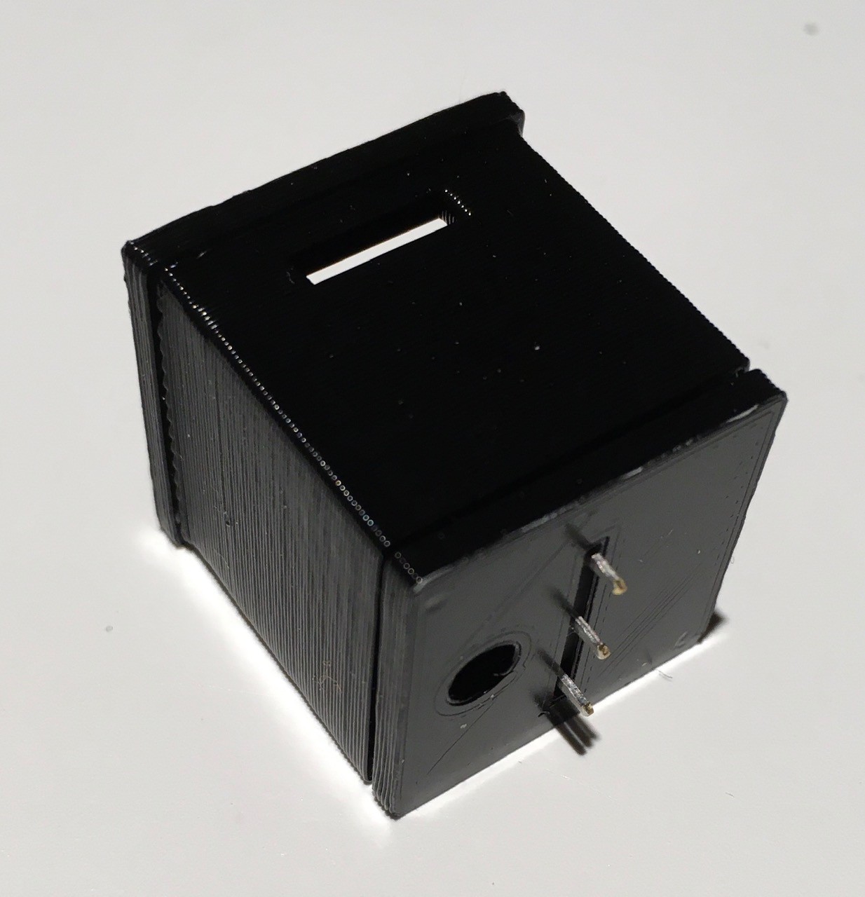
Note the orientation of the hole in the bottom of the base and the slot in the side of the console mounting piece. This is important.
Next slide the button shaft into the console mounting piece. Make sure that the slot on the button is aligned with the smaller slot at the top of the console mounting piece. Also make sure that the hole running down the shaft is aligned with the hole in the base.
Prepare the single NeoPixel unit by attaching short wires to the +5V, GND, Data In, and Data Out pads. I used 30 AWG wire for this.
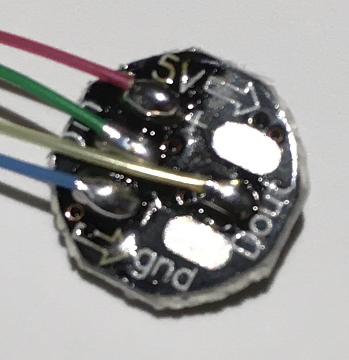
Carefully bend the wires so that they are both perpendicular to the PCB and off to one side. Then slide the wires all the way down the shaft and out through the base of the button.
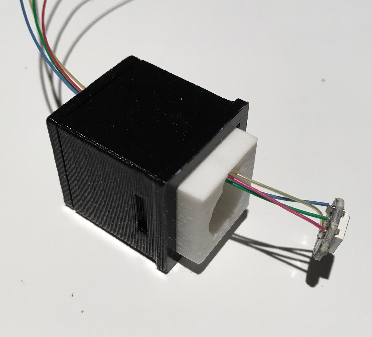
Push the wires and PCB all the way back until the PCB is inserted into the circular recess in the button shaft.
Slide the locking tab into the slot at the top to hold the shaft in place. This tab will also be used when it is time to panel mount the button.
I attached the LED's wires to a header for ease of use with this small gage wire.
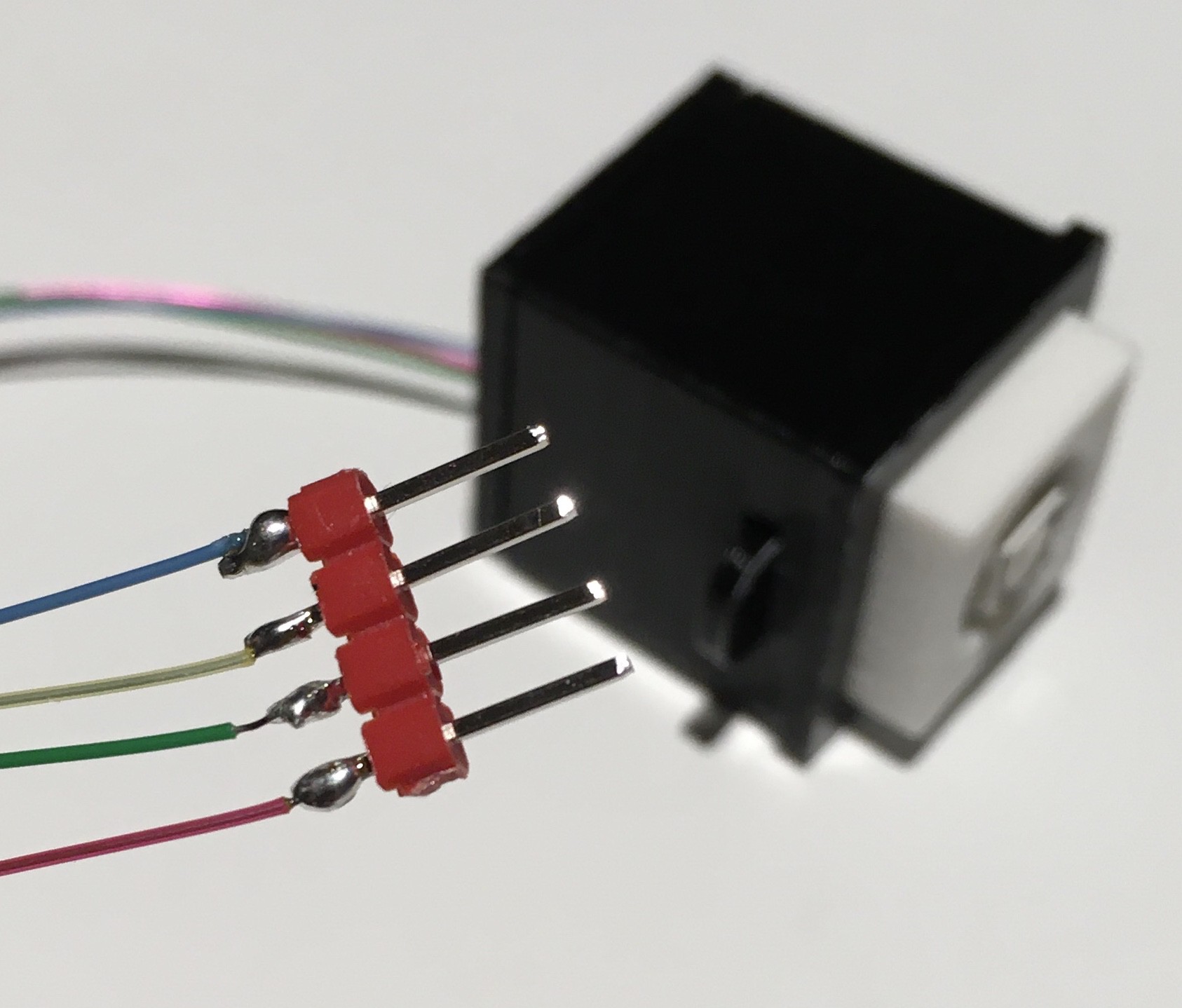
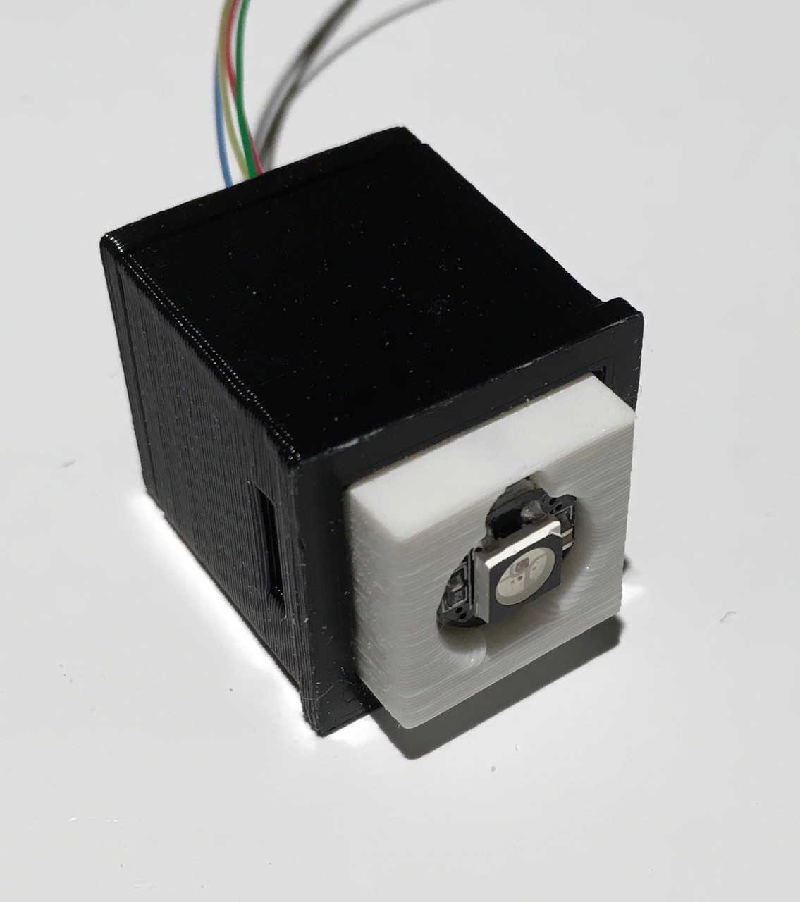
At this point since everything is still accessible, I would test the push button. When it has checked out you can glue the letter piece to the top of the shaft.

One down ten to go.
Testing the Push Button
I attached the microswitch and the NeoPixel to an Arduino Nano for testing. Here is the wiring list.
- NeoPixel 5v to Arduino 5V
- NeoPixel GND to Arduino GND
- NeoPixed Data In to Arduino D6
- Microswitch Common to Arduino GND
- Microswitch NO to Arduino D5
And I ran the following sketch:
#include "FastLED.h"

#define NUM_LEDS 1
#define LEDS_PIN 6
#define SWITCH_PIN 5
CRGB leds[NUM_LEDS];

int buttonPosition = 0;
boolean buttonDown = false;
int color = 0;

void setup() {
  Serial.begin(115200);
  Serial.println("Single LED");
  pinMode(SWITCH_PIN, INPUT_PULLUP);

  FastLED.addLeds<NEOPIXEL, LEDS_PIN>(leds, NUM_LEDS);
  leds[0] = CRGB::Black;
  FastLED.show();
}

void loop() {
  if (digitalRead(SWITCH_PIN) == LOW) {
    buttonPosition = (buttonPosition + 1) % 2;
    buttonDown = true;
  }
  if (buttonDown == true) {
    buttonDown = false;
    if (buttonPosition == 1) {
      if (color == 0) {
        leds[0] = CRGB::White;
      } else if (color == 1) {
        leds[0] = CRGB::Red;
      } else if (color == 2) {
        leds[0] = CRGB::Green;
      } else if (color == 3) {
        leds[0] = CRGB::Blue;
      }
      FastLED.show();
      color = (color + 1) % 4;
    } else {
      leds[0] = CRGB::Black;
      FastLED.show();
    }
    // Wait for button up.
    while (digitalRead(SWITCH_PIN) == LOW) delay(100);
  }
  delay(50);
}
Pushing the button consecutively turns the button light on and off, cycling through four colors each time it is turned on. Here is a short video of the button in action.
That's about it for the individual pieces of the project. It's time to start assembling what I have into a Think-a-Tron 2020.
Discussions
Become a Hackaday.io Member
Create an account to leave a comment. Already have an account? Log In.