 Michael Gardi
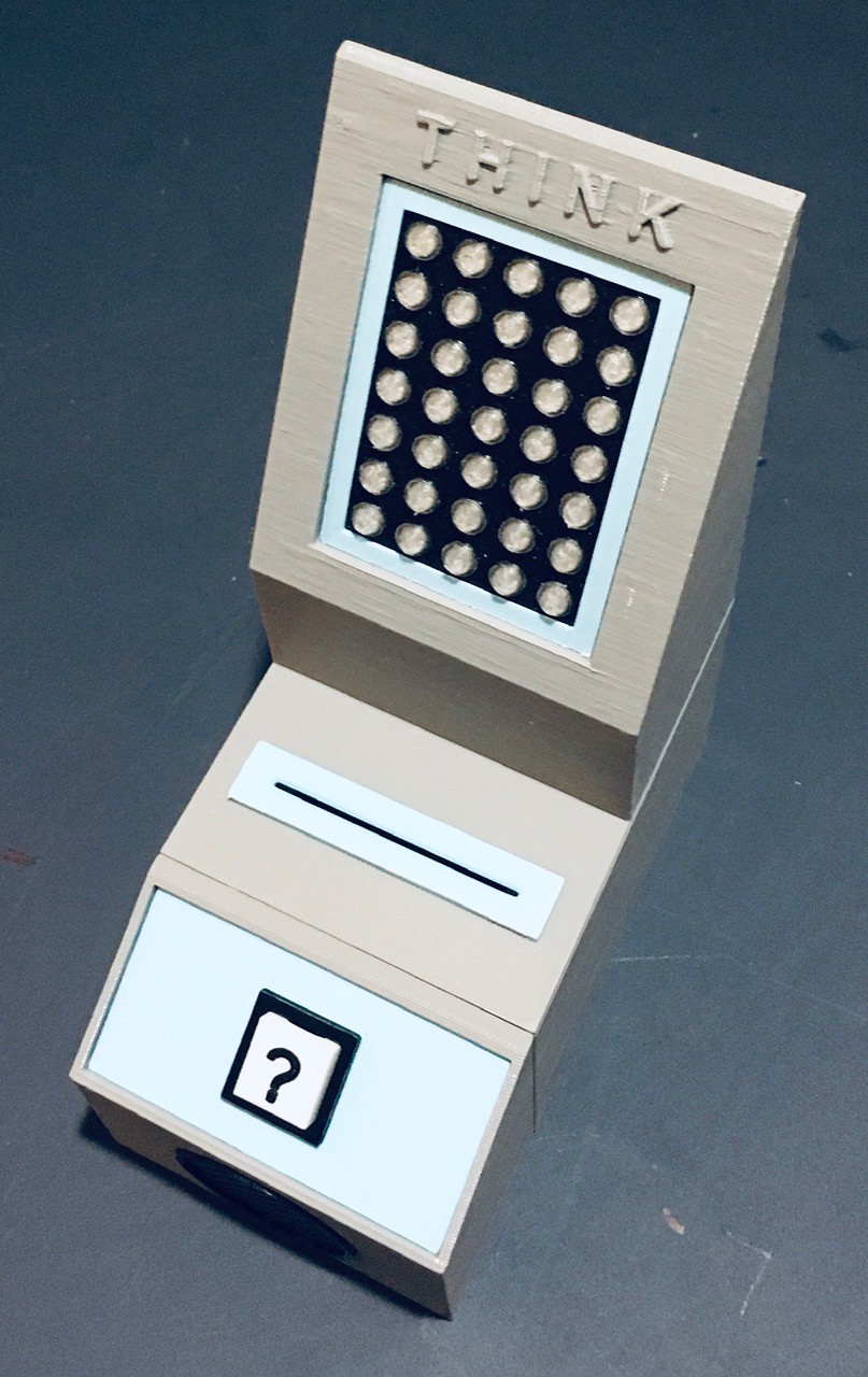
The heart of Think-a-Tron 2020 consists of three main parts: the camera QR code reader section, the display, and the question (?) console with speaker.
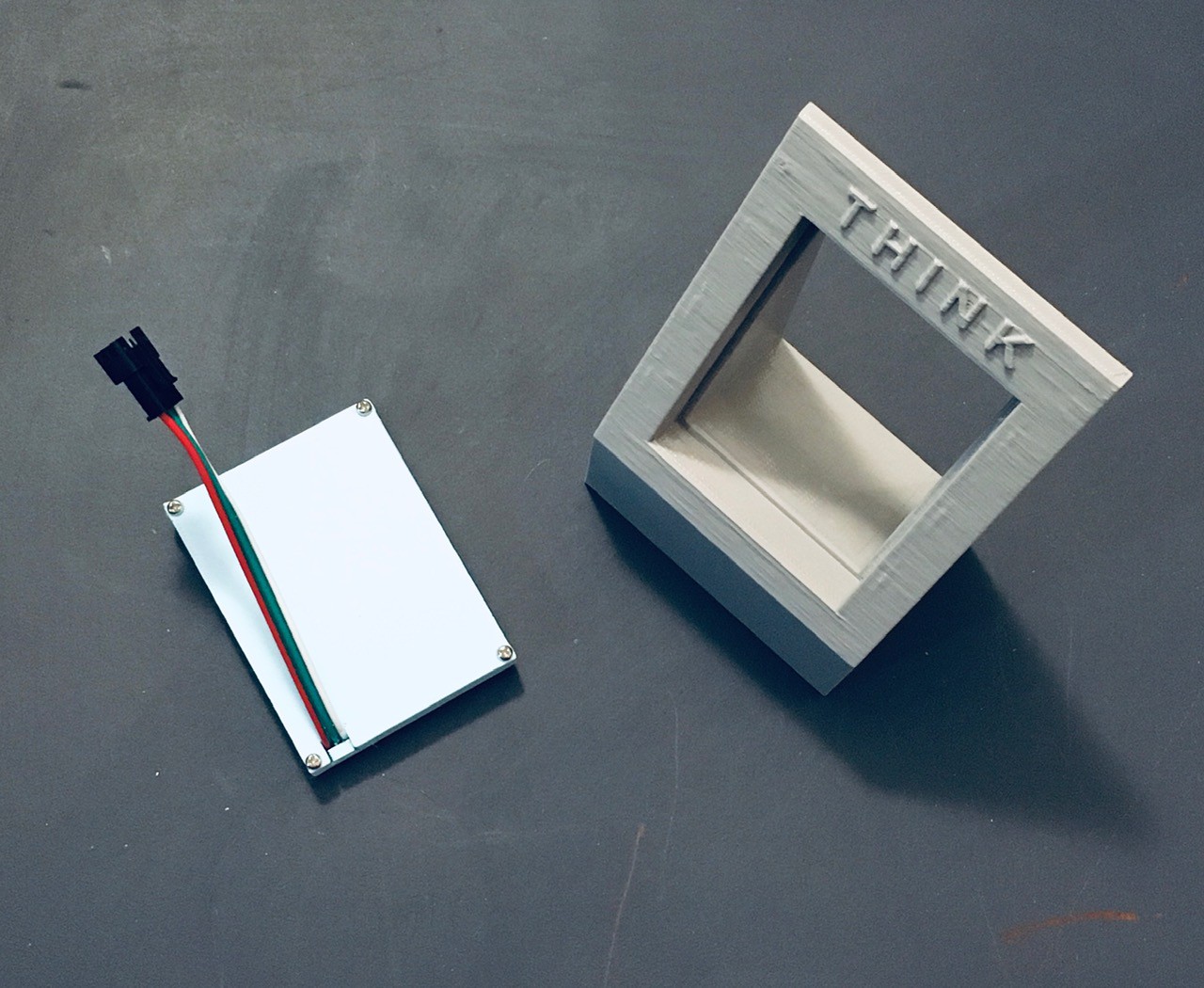
The ESP32-CAM is mounted in a rectangular box forming the main part of the core section.
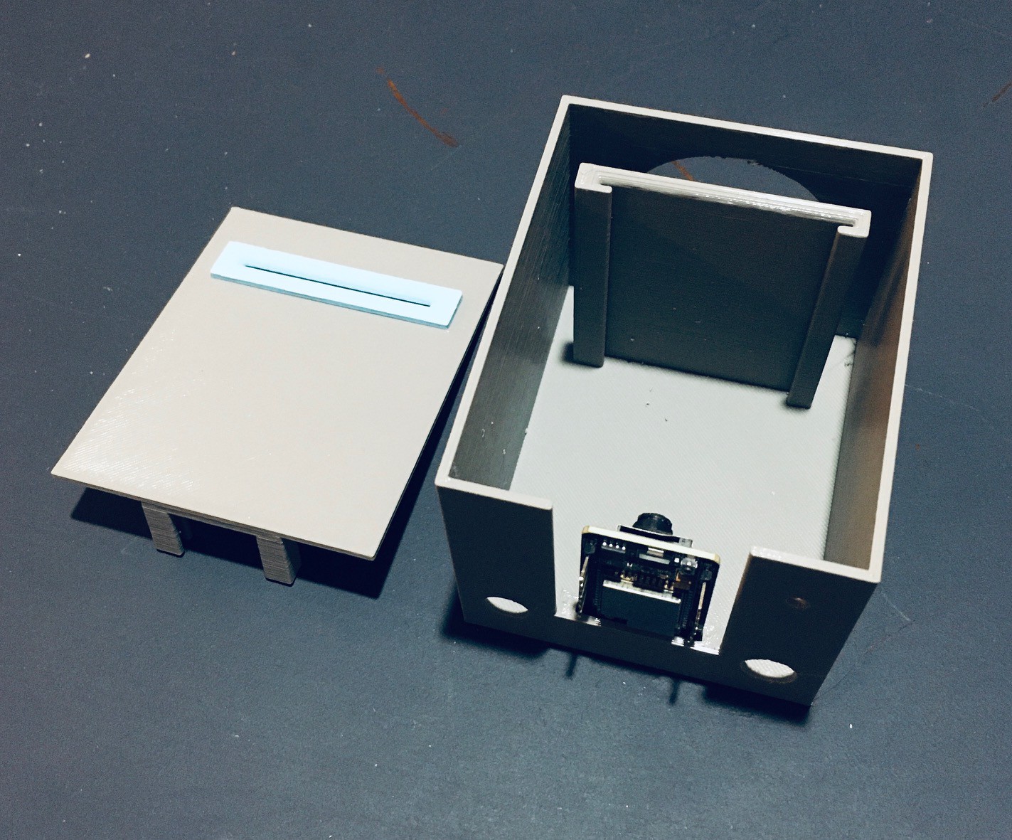
You can see there is a mounting slot for the ESP32-CAM and a guide to hold the question card (with QR code) at the correct distance for the camera to be able to read it. The top for this section has a slot that lines up with the guide to accept the card.
I had some buck converters lying around so I used one to power the project.
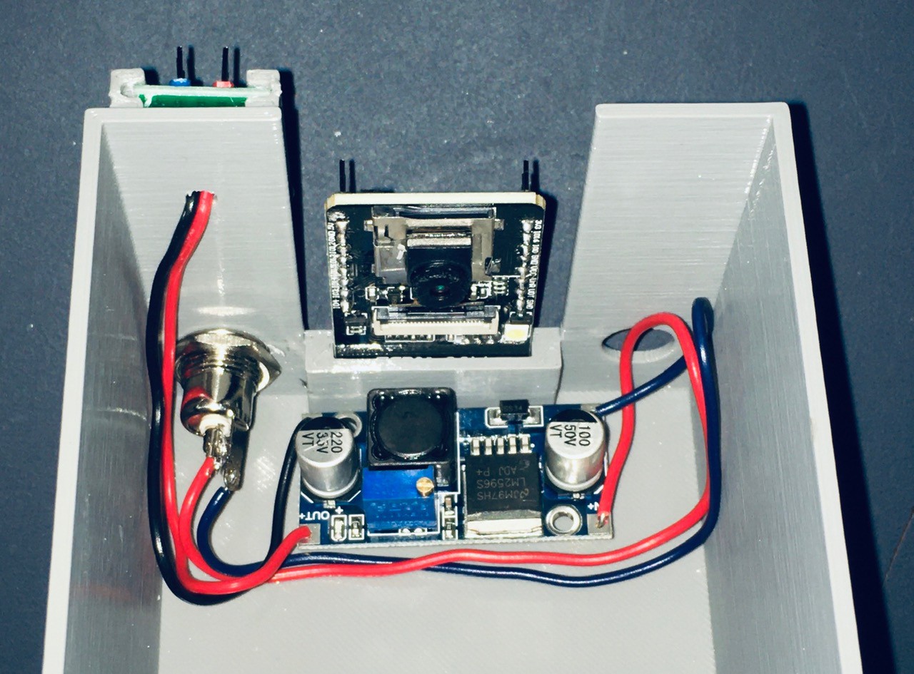
The power jack supplies the input voltage to the converter, with the output of 5V and GND connected o a small power rail that I made with headers and perf board. I mounted this with a small 3D printed bracket that I glued to the back.
I decided that I want to add a sound effect to the project so I purchased a cheap solid state recording and playback module (ISD1820 Sound Voice Recording Playback Module with Mic Sound Audio Microphone - Amazon).
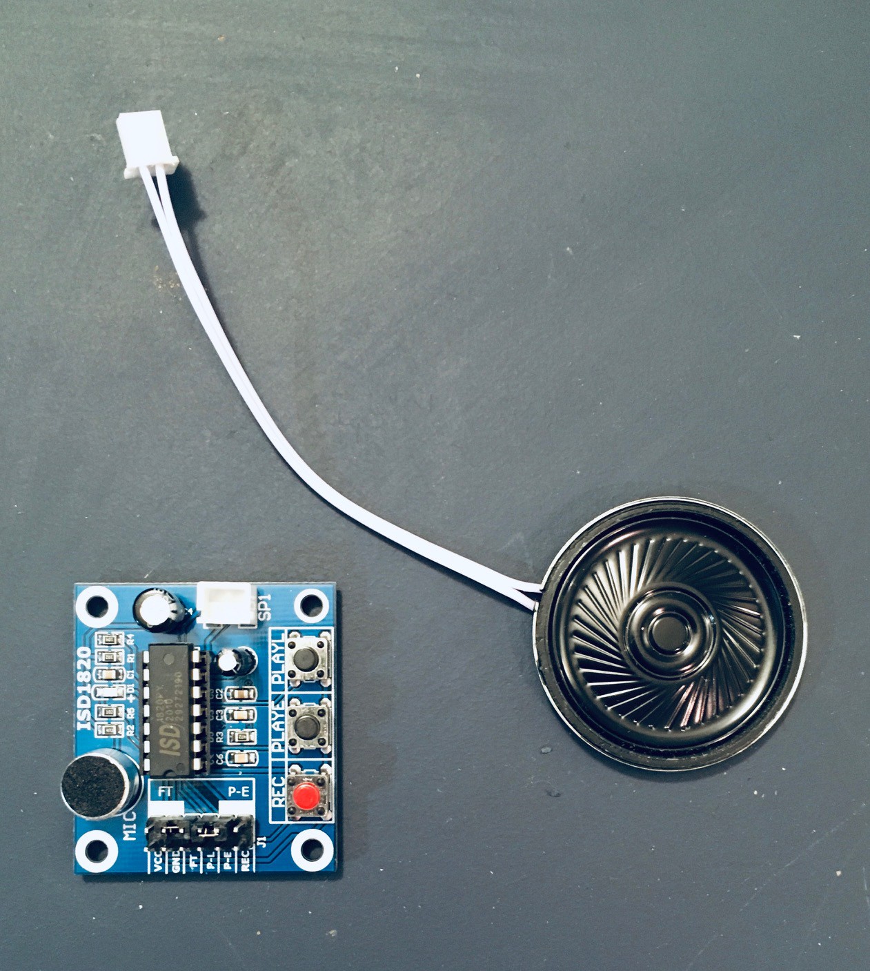
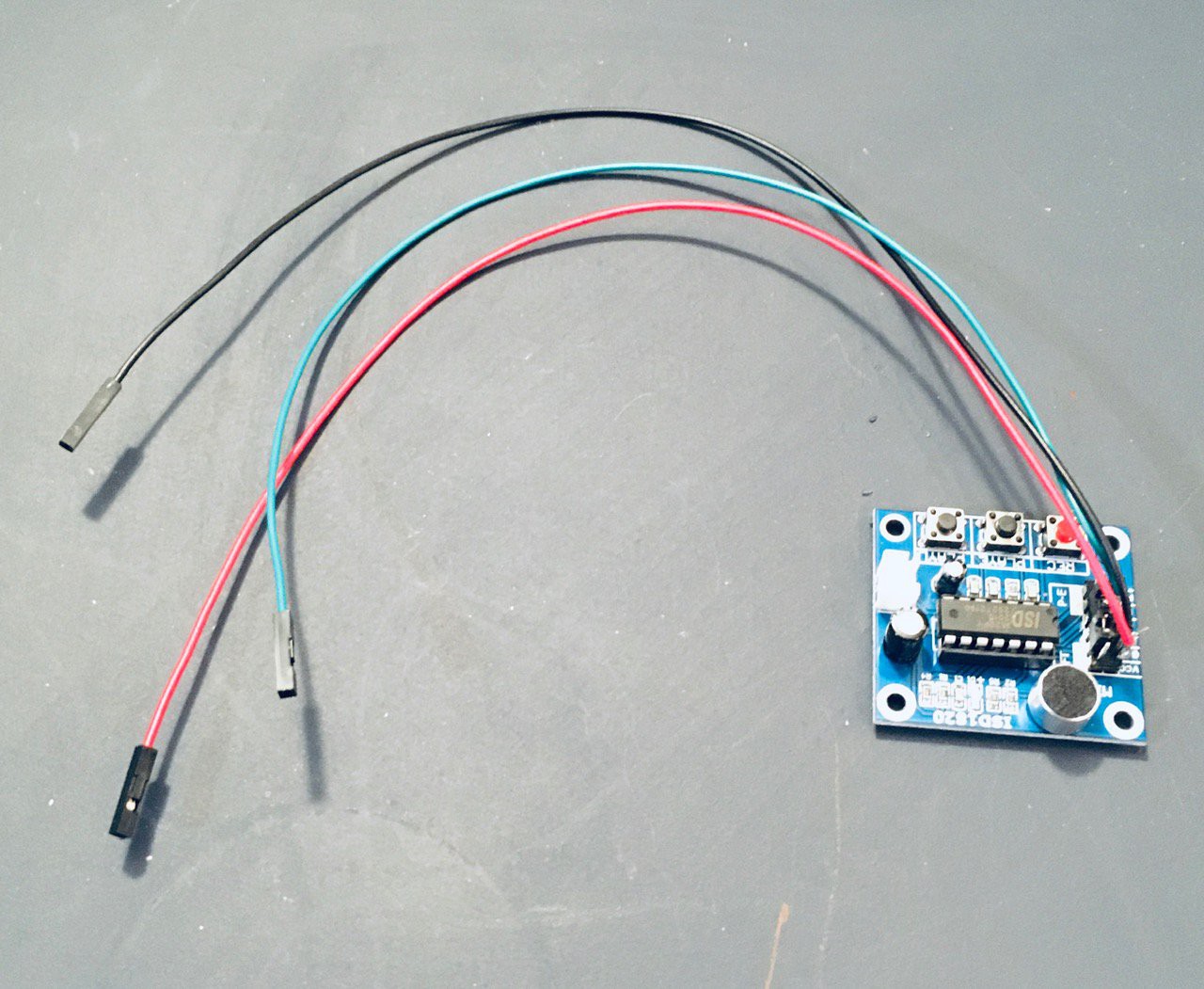
I attached some jumper wires to the VCC, GND, and P-L connectors. Whatever you record on the device (which can hold about 10 seconds of sound) will play back so long as the P-L pin is held high).
There is a slot for the sound module on the opposite side of the card holder.
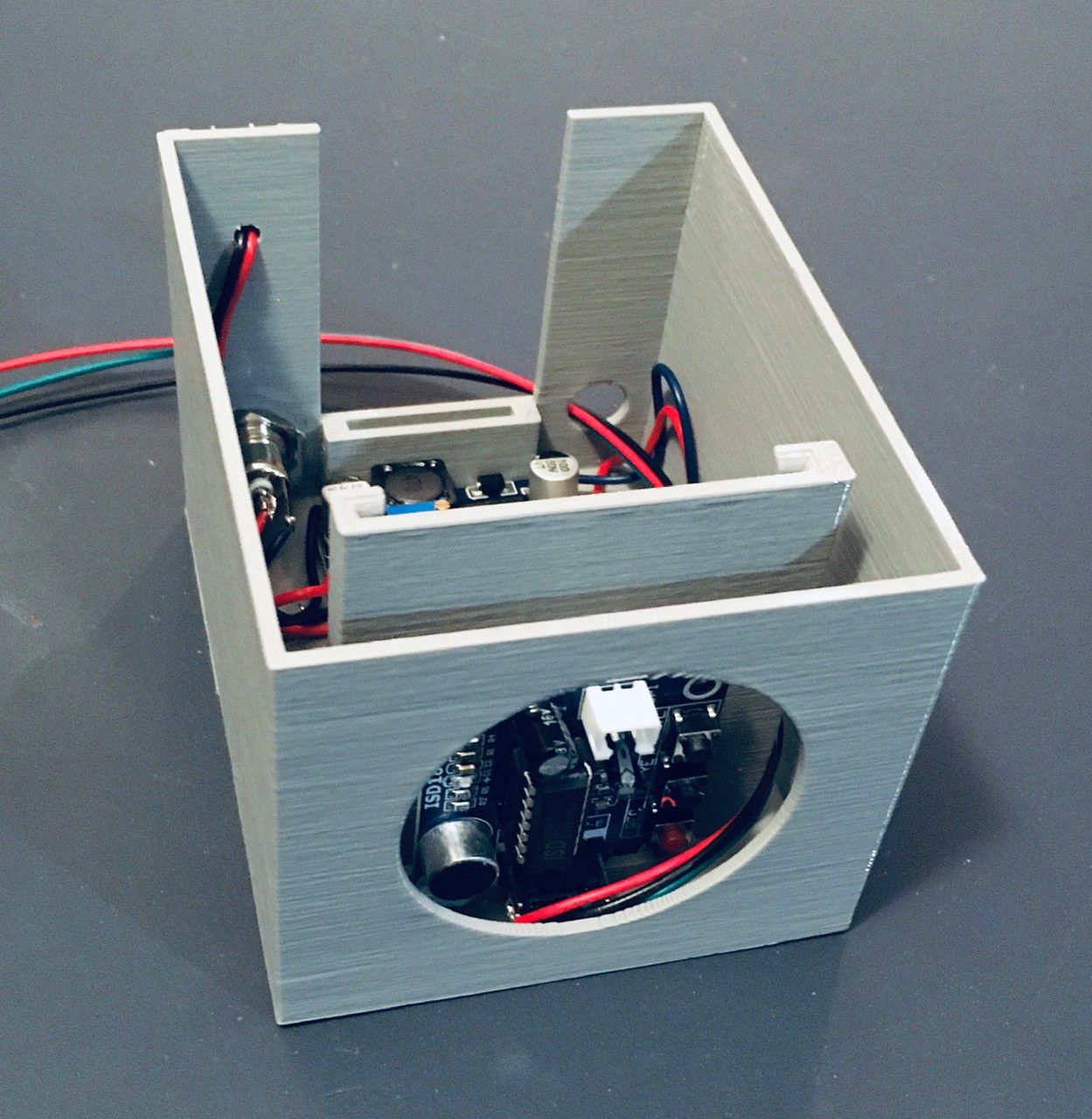
Run the jumpers along the left had side and out through the hole at the back as can be seen above. I secured the module with a piece of two sided tape.
I printed a small console to hold a single button and the speaker for the sound module.
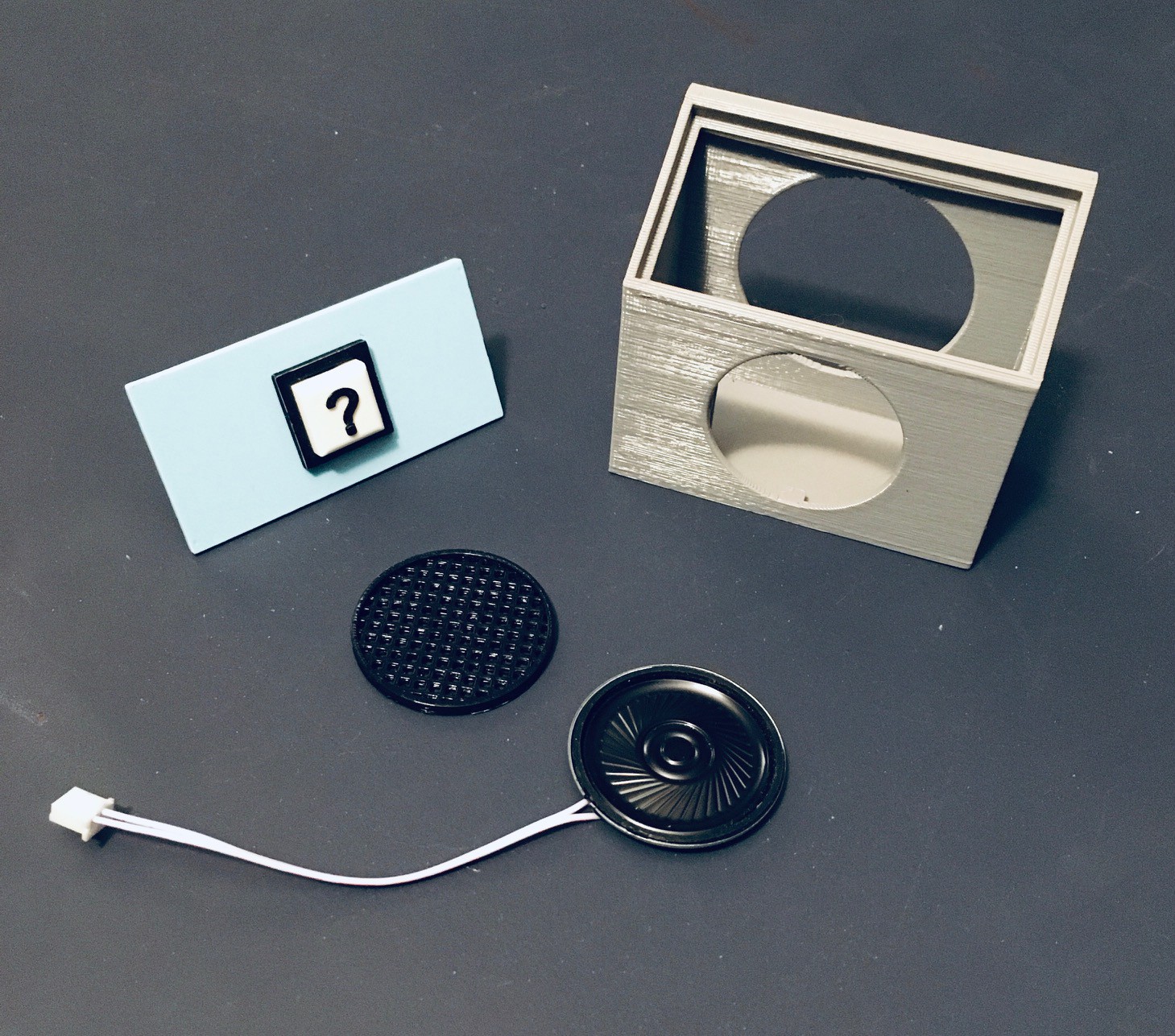
I attached the printed speaker grill to the console front with a few dabs of glue. There are slots to mount the speaker, which I secured in place with some electrical tape. I attached leads to the push button common and NO pins.
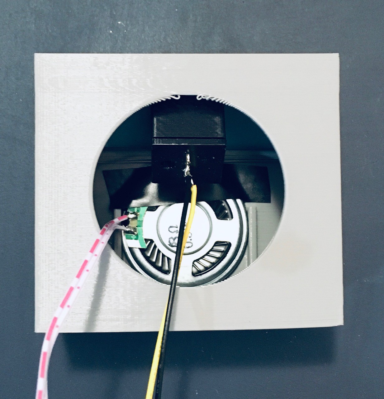
Attach the speaker to the sound module and run the push button cables along the side and out the back the same as was done with the sound module. Attach the button panel to the console. Glue the console to the main part of the core section.

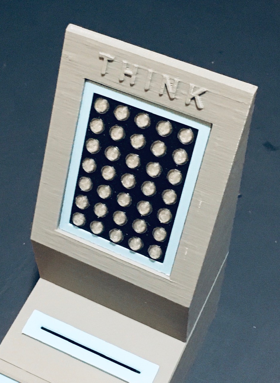
I printed a stand to hold the 5x7 NeoPixel display. I modified the wiring for the display case slightly so that the wires exited straight back instead of down.
Insert the display with case into the stand and glue the assembly to the top of main core section.
With everything assembled I wired the core unit up for a test.
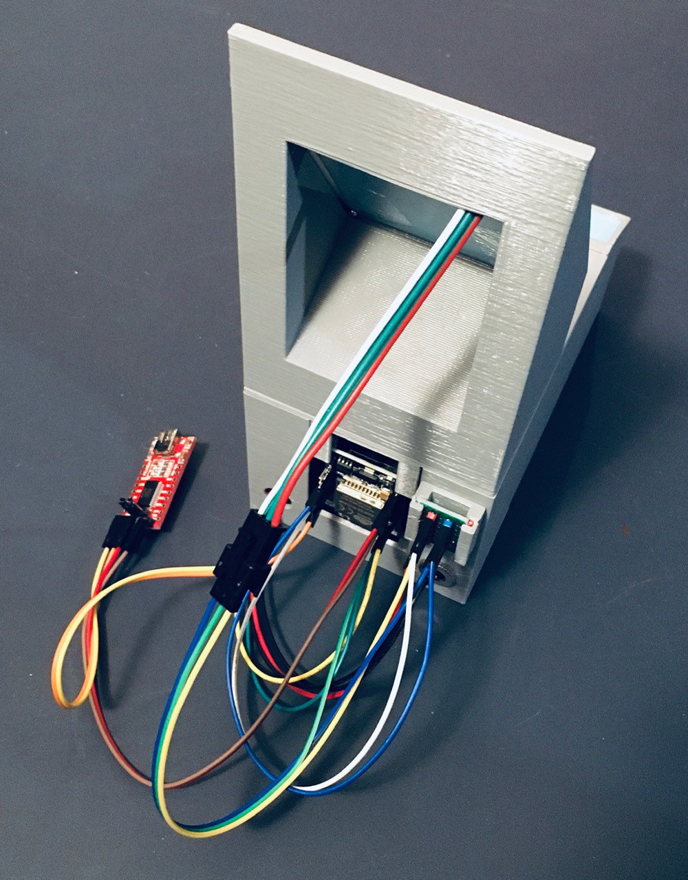
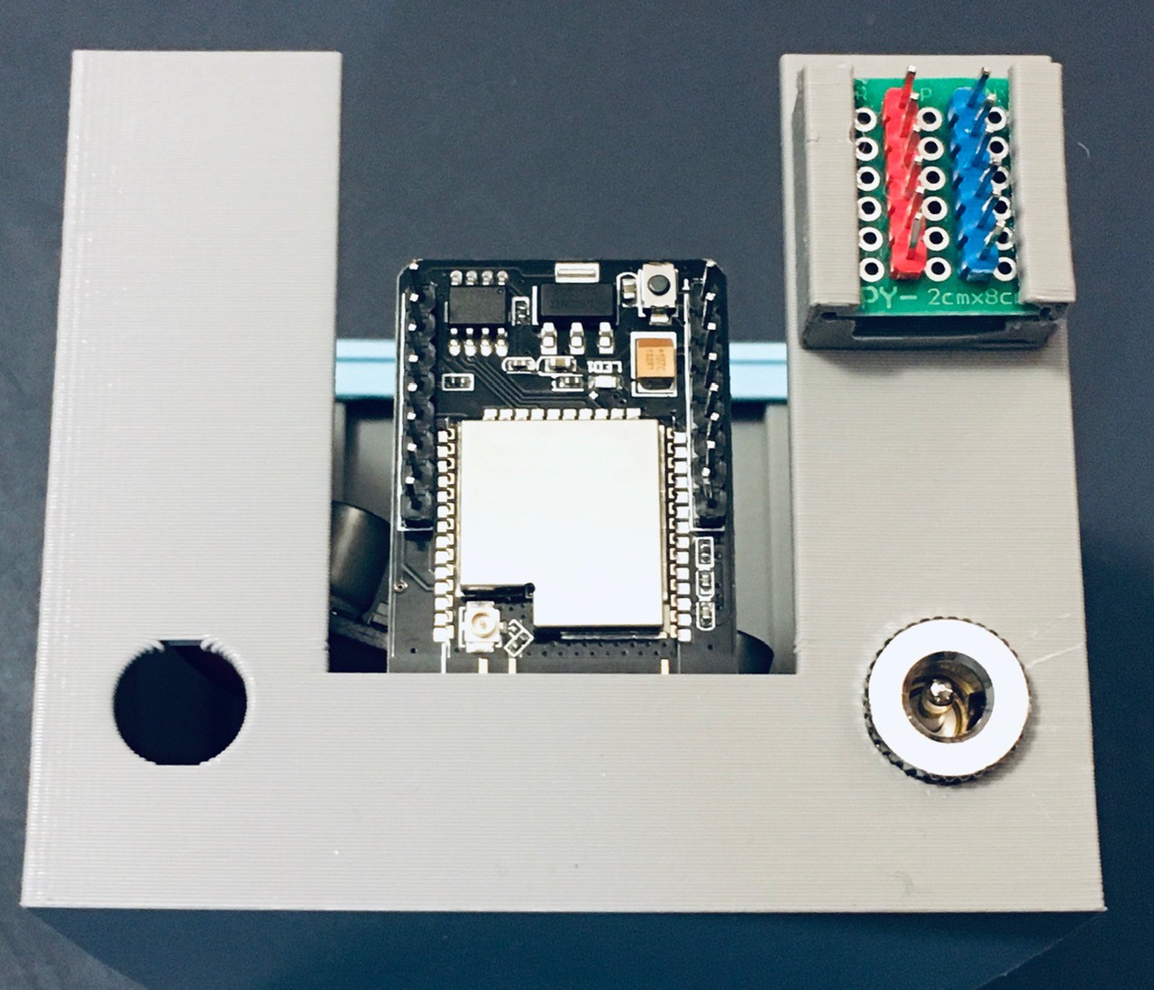
Mounting the ESP32-CAM this way makes it easy to access the headers and more importantly the reset button. I wrote an little "integration" test to exercise the components that I just added to the core unit.
#include "Adafruit_NeoPixel.h"
#include "ESPino32CAM.h"
#include "ESPino32CAM_QRCode.h"

// Camera objects.
ESPino32CAM cam;   // Image capture object
ESPino32QRCode qr; // Image decoding object

// Set the camera pins.
#define PWDN_GPIO_NUM     32
#define RESET_GPIO_NUM    -1
#define XCLK_GPIO_NUM      0
#define SIOD_GPIO_NUM     26
#define SIOC_GPIO_NUM     27
#define Y9_GPIO_NUM       35
#define Y8_GPIO_NUM       34
#define Y7_GPIO_NUM       39
#define Y6_GPIO_NUM       36
#define Y5_GPIO_NUM       21
#define Y4_GPIO_NUM       19
#define Y3_GPIO_NUM       18
#define Y2_GPIO_NUM        5
#define VSYNC_GPIO_NUM    25
#define HREF_GPIO_NUM     23
#define PCLK_GPIO_NUM     22

// Think-a-Tron Controls.
#define FLASH 4
#define SOUND 14
#define QUESTION 15


// 5x7 LED Array.
#define NUM_LEDS 35
#define LEDS_PIN 2
Adafruit_NeoPixel matrix(NUM_LEDS, LEDS_PIN, NEO_GRB + NEO_KHZ800);

int A[35] = {0,0,1,1,1,1,1,
             0,1,0,0,1,0,0,
             1,0,0,0,1,0,0,
             0,1,0,0,1,0,0,
             0,0,1,1,1,1,1};

int B[35] = {1,1,1,1,1,1,1,
             1,0,0,1,0,0,1,
             1,0,0,1,0,0,1,
             1,0,0,1,0,0,1,
             0,1,1,0,1,1,0};

int C[35] = {0,1,1,1,1,1,0,
             1,0,0,0,0,0,1,
             1,0,0,0,0,0,1,
             1,0,0,0,0,0,1,
             0,1,0,0,0,1,0};

int T[35] = {1,0,0,0,0,0,0,
             1,0,0,0,0,0,0,
             1,1,1,1,1,1,1,
             1,0,0,0,0,0,0,
             1,0,0,0,0,0,0};

int F[35] = {1,1,1,1,1,1,1,
             1,0,0,1,0,0,0,
             1,0,0,1,0,0,0,
             1,0,0,1,0,0,0,
             1,0,0,0,0,0,0};

int Q[35] = {0,1,0,0,0,0,0,
             1,0,0,0,0,0,0,
             1,0,0,0,1,0,1,
             1,0,0,1,0,0,0,
             0,1,1,0,0,0,0};

String lastResult = "";

void setup() {
   // Define the sound pin.
  pinMode(SOUND, OUTPUT);
  digitalWrite(SOUND, LOW); // Set sound off.

  // Serial debugging.
  Serial.begin(115200);
  Serial.println("QR Code Reader");

  // Define the flash pin.
  pinMode(FLASH, OUTPUT);
  digitalWrite(FLASH, LOW); // Turn off the flash.

  // Define the question button pin.
  pinMode(QUESTION, INPUT_PULLUP);

  // Configure the camera pins.
  camera_config_t config;
  config.ledc_channel = LEDC_CHANNEL_0;
  config.ledc_timer = LEDC_TIMER_0;
  config.pin_d0 = Y2_GPIO_NUM;
  config.pin_d1 = Y3_GPIO_NUM;
  config.pin_d2 = Y4_GPIO_NUM;
  config.pin_d3 = Y5_GPIO_NUM;
  config.pin_d4 = Y6_GPIO_NUM;
  config.pin_d5 = Y7_GPIO_NUM;
  config.pin_d6 = Y8_GPIO_NUM;
  config.pin_d7 = Y9_GPIO_NUM;
  config.pin_xclk = XCLK_GPIO_NUM;
  config.pin_pclk = PCLK_GPIO_NUM;
  config.pin_vsync = VSYNC_GPIO_NUM;
  config.pin_href = HREF_GPIO_NUM;
  config.pin_sscb_sda = SIOD_GPIO_NUM;
  config.pin_sscb_scl = SIOC_GPIO_NUM;
  config.pin_pwdn = PWDN_GPIO_NUM;
  config.pin_reset = RESET_GPIO_NUM;
  config.xclk_freq_hz = 20000000;
  config.pixel_format = PIXFORMAT_JPEG;
  config.frame_size = FRAMESIZE_VGA;
  config.jpeg_quality = 4;
  config.fb_count = 1;

  // Setup the camera.
  esp_err_t err = esp_camera_init(&config); // Initialize the camera.
  if (err != ESP_OK) {
    Serial.printf("Camera start failed with error 0x%x", err);//Informa erro se a câmera não for iniciada corretamente
    delay(1000);
    ESP.restart(); // Reboot the ESP
  }

  // Initialize the decoding object.
  qr.init(&cam);
  sensor_t *s = cam.sensor();
  s->set_framesize(s, FRAMESIZE_CIF);
  s->set_whitebal(s, true);

  // Setup the 5x7 LED Array.
  matrix.begin();
  matrix.show(); // Initialize all pixels to 'off'.
  showLetter(Q);

  // Announce.
  Serial.println();
  Serial.println("Think-a-Tron 2020 Ready.");
}

void loop(){
  unsigned long pv_time  = millis();

  // Captura an image.
  digitalWrite(FLASH, HIGH); // Turn on the flash.
  for (int i = 0; i < 10; i++) {
    if (digitalRead(QUESTION) == LOW) {
      showLetter(Q);
      lastResult = "";
    }
    delay(40);
  }
  camera_fb_t *fb = cam.capture();
  digitalWrite(FLASH, LOW); // Turn off the flash.
  if (!fb) {
    Serial.println("Image capture failed.");
    return;
  }

  // Attempt to read a QR code from the image.
  dl_matrix3du_t *rgb888, *rgb565;
  if (cam.jpg2rgb(fb, &rgb888)) {
    rgb565 = cam.rgb565(rgb888);
  }
  cam.clearMemory(rgb888);
  cam.clearMemory(rgb565);
  dl_matrix3du_t *image_rgb;
  if (cam.jpg2rgb(fb, &image_rgb)) {
    cam.clearMemory(fb);

    qrResoult res = qr.recognition(image_rgb); // Decodes the image containing the data.

    if (res.status) { // If you can decode the image it shows the data on the screen.
      String result = res.payload; // Variable to show the data contained in the QR Code.
      if (result != lastResult) {
        lastResult = result;
        if (res.payload == "A") {
            showRandom(); showLetter(A);
        } else if (res.payload == "B") {
            showRandom(); showLetter(B);
        } else if (res.payload == "C") {
            showRandom(); showLetter(C);
        } else if (res.payload == "T") {
            showRandom(); showLetter(T);
        } else if (res.payload == "F") {
            showRandom(); showLetter(F);
        } else {
            showLetter(Q);
        }
      }
      Serial.println();
      Serial.println(result);  // Shows data on the serial monitor.
    }
    else { // If you do not wait to receive code.
       Serial.println();
       Serial.println("Waiting for code.");
    }
  }

  cam.clearMemory(image_rgb); // Delete image to receive a new image.
}

// Display the letter passed on the 5x7 LED Array.
void showLetter(int letter[]) {
  for (int i = 0; i < NUM_LEDS; i++) {
    if (letter[i] == 1) {
      matrix.setPixelColor(i, 32, 32, 32);
    } else {
      matrix.setPixelColor(i, 0, 0, 0);
    }
  }
  matrix.show();
}

// Show a random changing pattern on the 5x7 LED Array.
void showRandom() {
  // Trigger the sound.
  digitalWrite(SOUND, HIGH);
  for (int count = 0; count <110; count++) {
    for (int i = 0; i < NUM_LEDS; i++) {
      if (random(3) == 0) {
        matrix.setPixelColor(i, 32, 32, 32);
      } else {
        matrix.setPixelColor(i, 0, 0, 0);
      }
    }
    matrix.show();
    delay(50);
  }
  digitalWrite(SOUND, LOW);
}
And here is what that test looks like.
I'm coming down to the wire. I just have to incorporate the player one and two panels and the hardware and software will be done.
Discussions
Become a Hackaday.io Member
Create an account to leave a comment. Already have an account? Log In.