 Ted Yapo
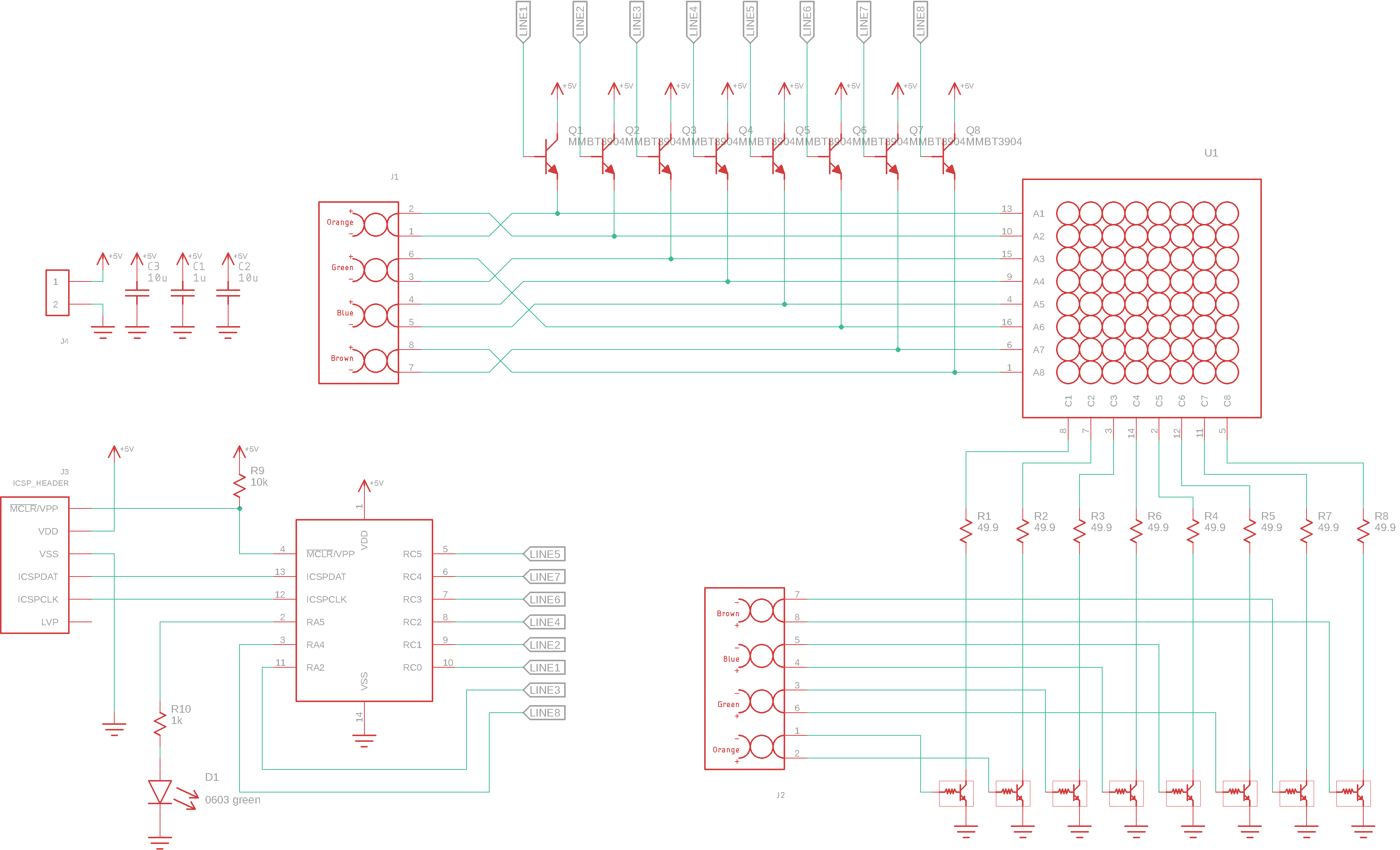
I actually needed a 6P4C cable tester, which I haven't assembled yet, but I couldn't help but build this one first, because it seemed like such a perfect use for an 8x8 LED matrix. The idea is simple: the right ends of the cable lines are connected to the bases of NPN low-side switches, driving common-cathode columns of the LED matrix. You energize one row of the matrix, which is also connected to a conductor on the left end of the cable. This displays zero or more LEDs in the row which are connected to this particular RJ45 pin. If you scan through the rows in this way, you get the full 8x8 connectivity of the cable.
The Eagle files for the schematic and PCB are in the files section of this project, as is a zip file with the gerbers if you want to have your own made. As it stands, it will require a PIC programmer to get working, since I used a PIC16F1705 to scan the rows. If you'd rather make a code-free version, see the notes below. This should work well with a 555 and 74HC4017 instead of the PIC.
Now, let's have a look at some common cables.
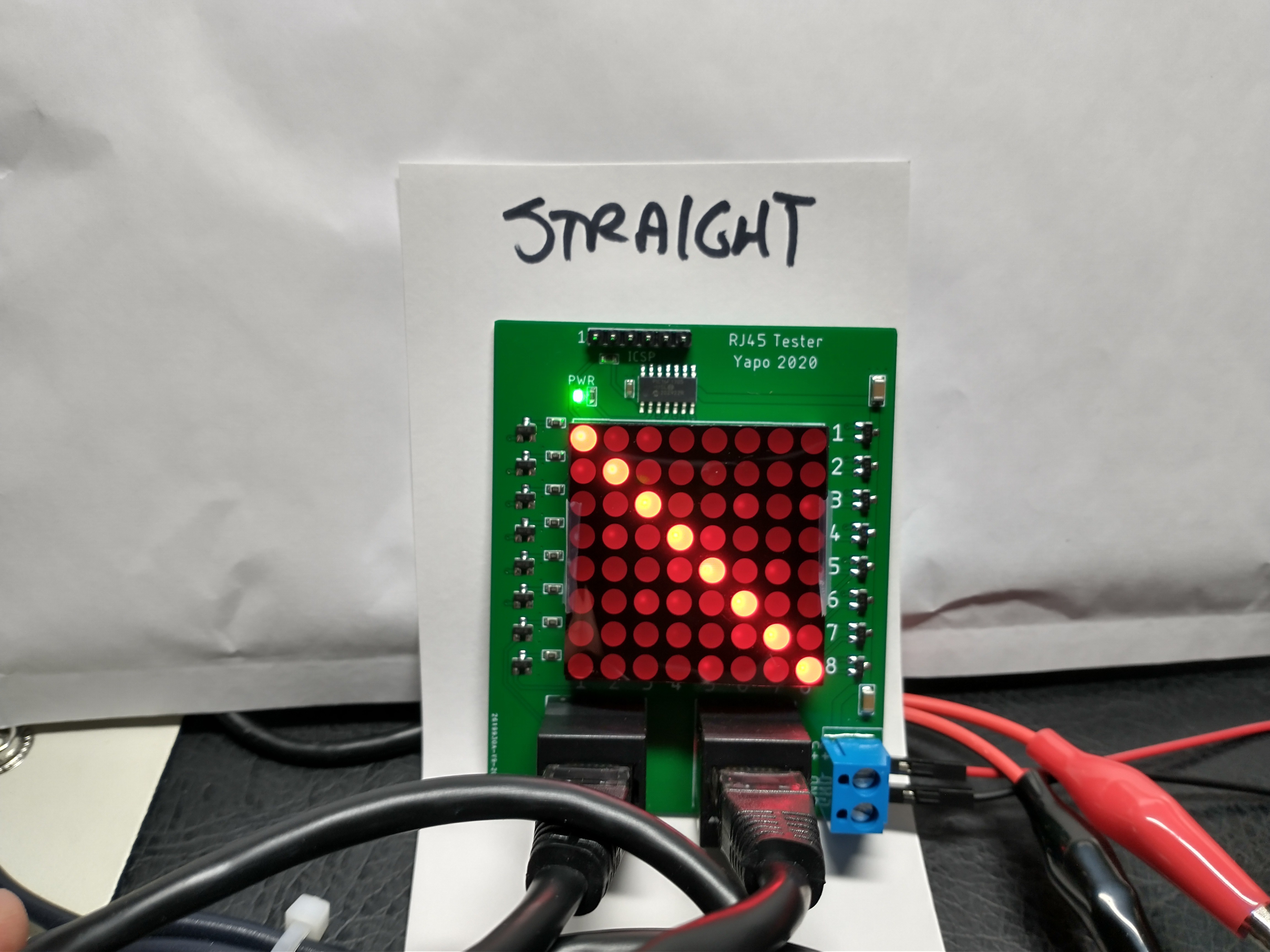
Straight Cable
Here's the "normal" ethernet patch cord, aka a straight cable. Pin 1 on one side is connected to pin 1 of the other side, etc.
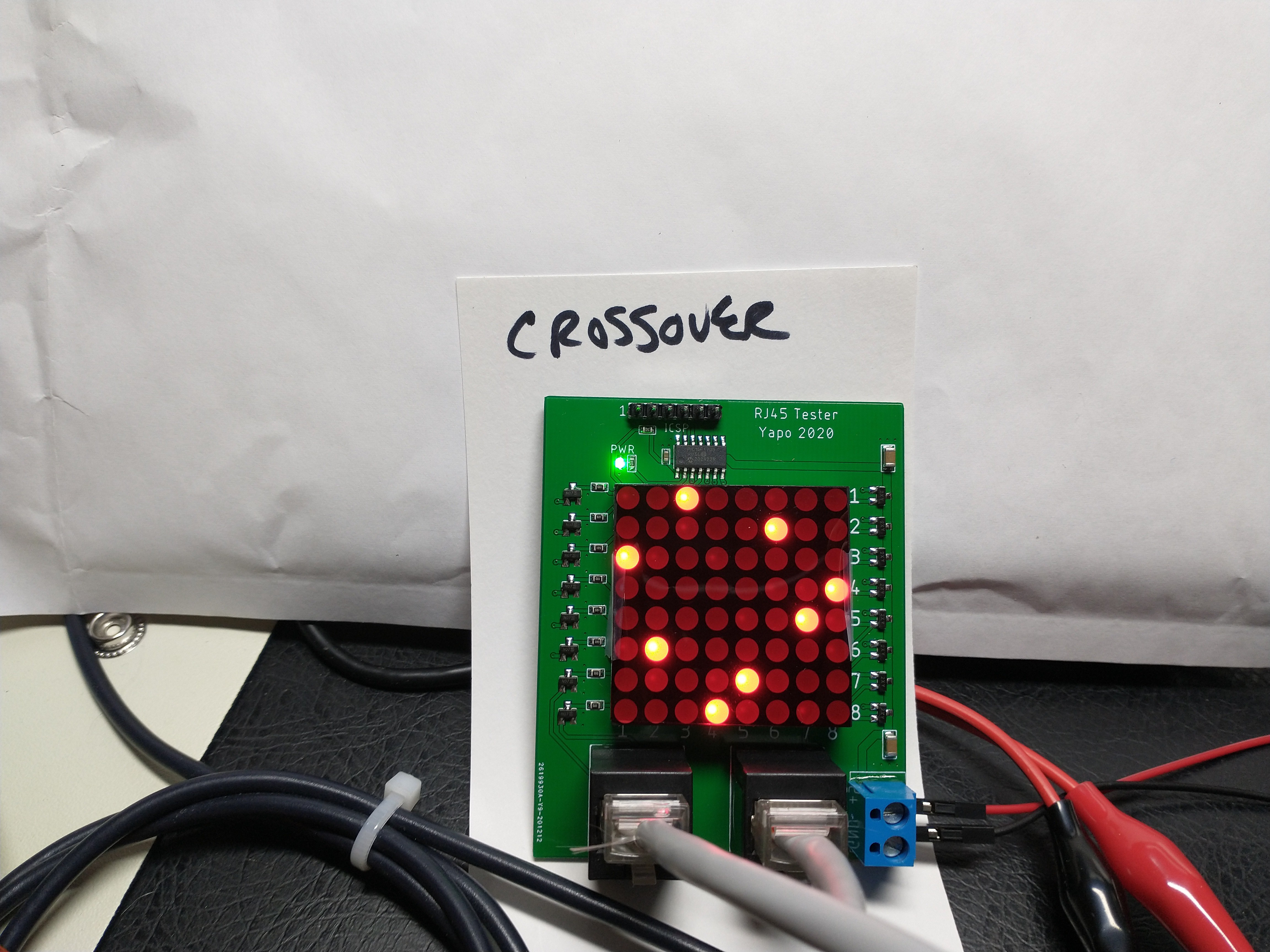
Crossover Cable
This is a crossover cable, which swaps TX and RX pairs. You used to need this if you wanted to connect two networked devices without a switch. Modern ethernet ports can figure this kind of thing out on their own.
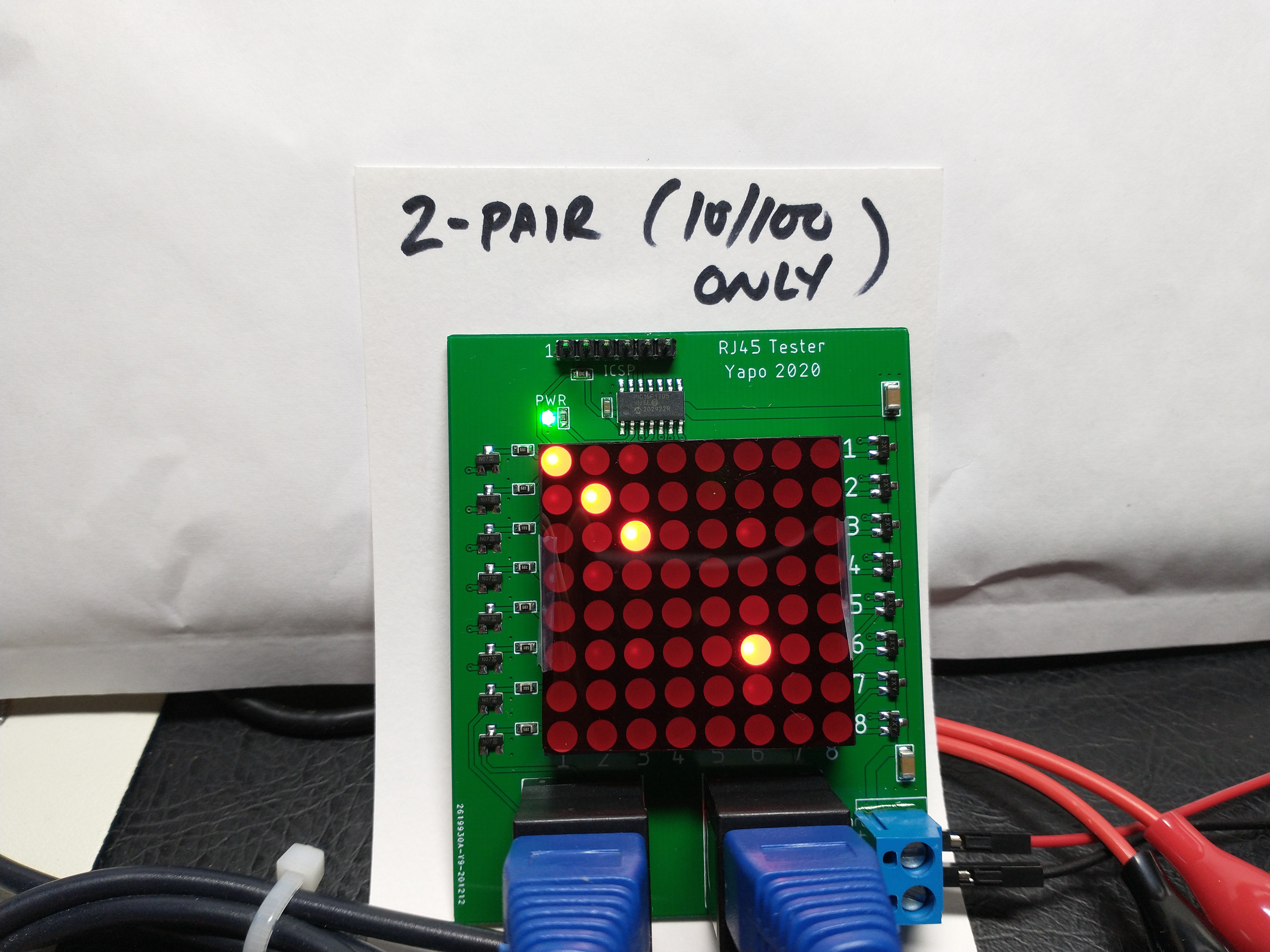
Old 10/100 Cable
This is an ancient cable that I think came in a box with a router maybe 20 years ago. As you can see, it only has two pair connected, so can only be used for 10 or 100 Mbps connections. GigE requires all four pair.
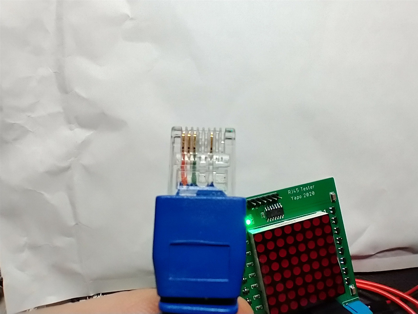
You can see there are only four wires in the thing if you look closely at the ends:
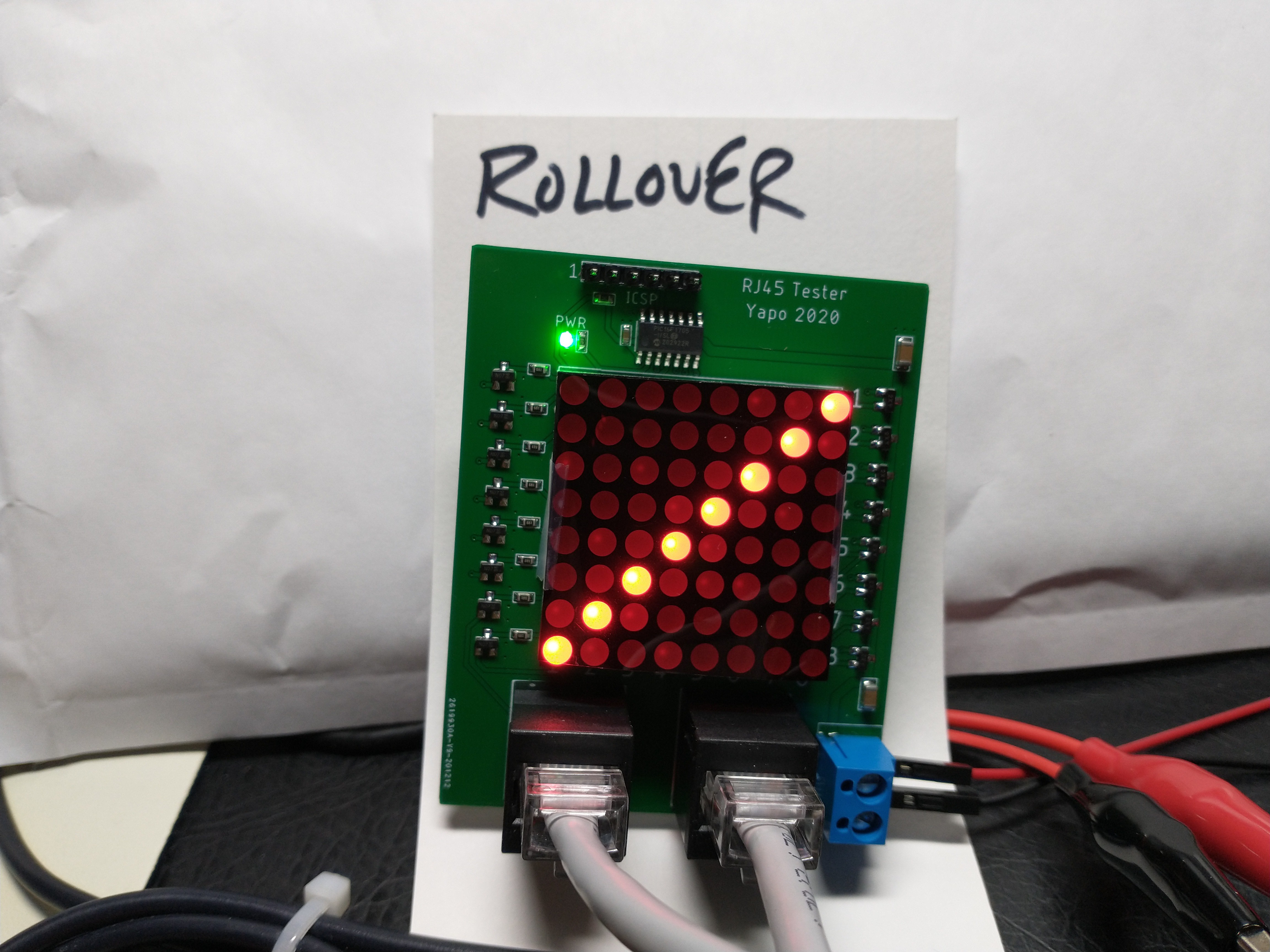
Rollover Cable
This is a rollover cable, in which pins 1-8 are reversed at the far end. You see these sometimes in RS232 applications for RJ45 connectors, but much more often with the smaller modular connectors like RJ11.
The Circuit
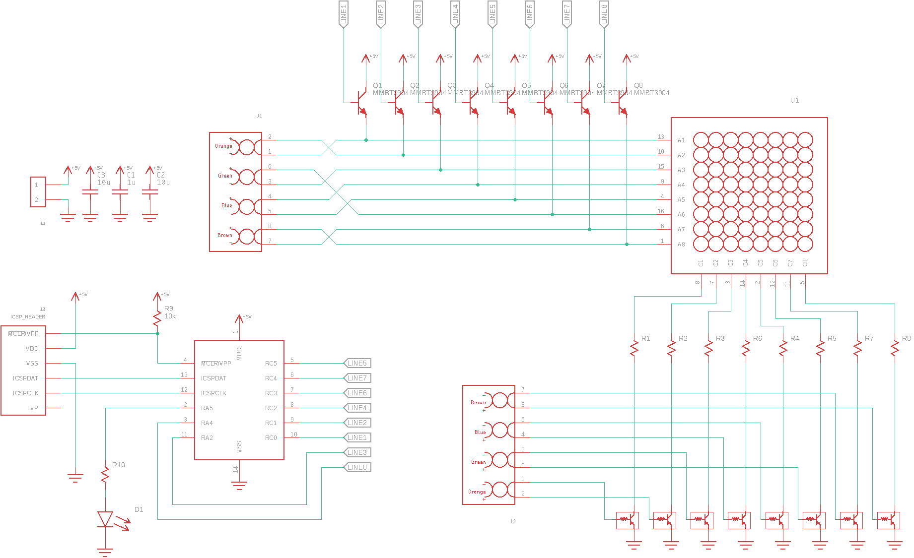
As discussed above, the circuit scans common-anode rows of the matrix. A set of eight emitter followers provides enough drive for the row, because it's possible that all eight LEDs need to illuminate. The row lines are also connected to one end of the cable.
The other end of the cable drives some NPN switches. I used pre-biased transistors in SOT23 cases to save space on the PCB, and also because I have a bag full of them. R1-R8 are 49.9 ohms. This yields about 40 mA peak drive for the LEDs, and since they have a 1/8 duty cycle, results in a decent brightness.
I chose a PIC16F1705 to do the scanning, and while you could argue it's overkill for this circuit, it was fast and easy to get working.
I toyed with the idea of using a 555 and 74HC4017 to scan the rows, which might look more at home in this circuit, and would also give the instant gratification of soldering and testing without a firmware cycle interrupting the fun, but decided to stay in the present and just use a microcontroller.
Beyond Connectivity
When scanned at slow speeds -- just high enough so the display doesn't flicker -- the LEDs show the continuity between ends of the cable. If you turn up the scanning speed into the hundreds of kHz or low MHz range, something more interesting happens:
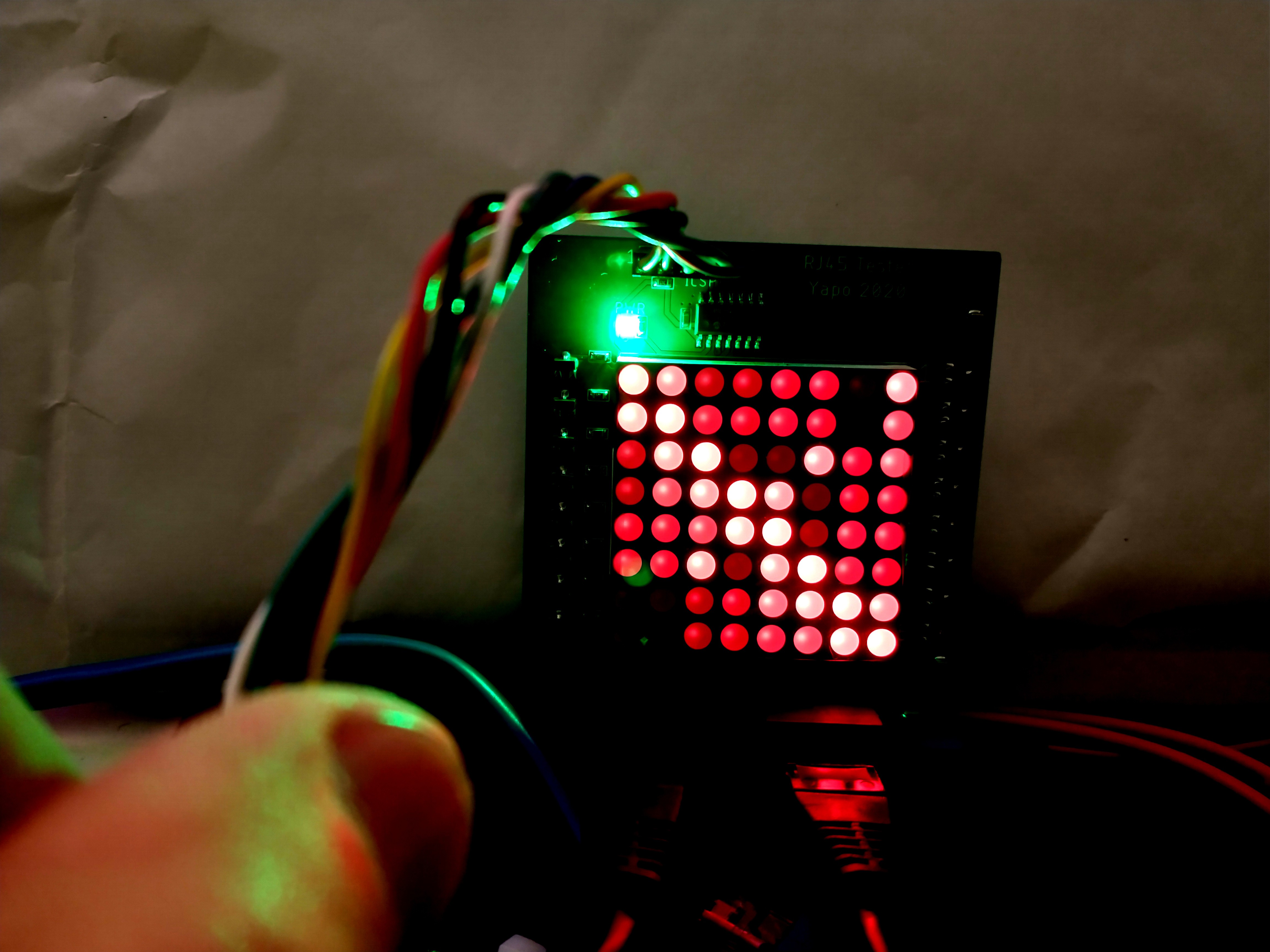
Now, you start to see capacitive effects between the conductors. In this case, a straight cable wired according to T568B is shown. This cable has the green pair on pins 3 and 6, while all the other pairs are on neighboring pins. You can clearly see a coupling between conductors 3 and 6 -- note the bright LEDs at (3,6) and (6.3). This happens because these wires, the green pair in this case, are twisted together and present a capacitance between them. This capacitance is enough to couple signal between them and cause the 3 LED to light when the 6 line is energized and vice versa.
Of course, the intensities of the LEDs in this case are a little random, since the LEDs themselves may not be brightness...
Read more »


 Yann Guidon / YGDES
 Grant Stankaitis
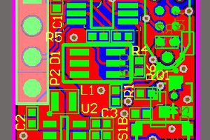
 FrazzledBadger
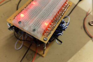
Hey Ted,
I have been wanting to recreate this project but also add a few other features that would make it an all in one cable testing solution.
I have tried to use digital simulator and some more conventional simulator and they really don't like the circuit for some reason. Did you use a simulator when you designed yours and if you did what did you use?
Thanks,
Ender