 doctek
The latest ST changes to the variant structure are now included. This all works with version 2.6.0. See Project Log Revising to Latest ST Software Design for all the details.
Project Log Using the tArmDuino Serial Capability has been added to show how to use serial.
9/19/23
----------------------------------------------------------------------------------------------------------------------------------------------------
Once again finding myself in need of a tiny, cheap, yet powerful Arduino that didn't seem to exist, I decided to create one. What a tiny Arduino should provide is access to as many Arduino hardware features as possible, plenty of flash memory, a programming connection, and a small board size. An ARM with 3.3V I/O seems like the right processor choice, and STMicrosystems makes a huge selection. Program development is done with the Arduino environment since ST has provided libraries for Arduino. Why use Arduino? Libraries can do many tasks and save development time allowing me to focus on "value added" tasks without having to build infrastructure first.
Studying the STM32 product line, I narrowed down my possible choices to the STM32L0 series. My intent was to choose a processor that provided most (possibly all) of the capabilities of an Arduino UNO, with more memory if possible, all while being suitable for battery power. I was not concerned with having more I/O, so a 28 or 32 pin version seemed satisfactory. The STM32L031G6 seemed like a good choice and was my first design. For reasons I'll discuss, the STM32L071KB emerged as a better choice.
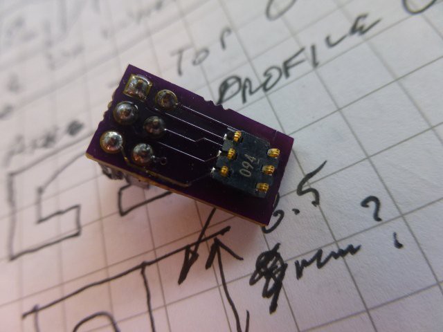
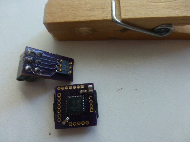
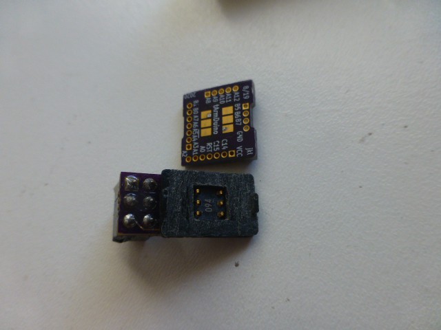
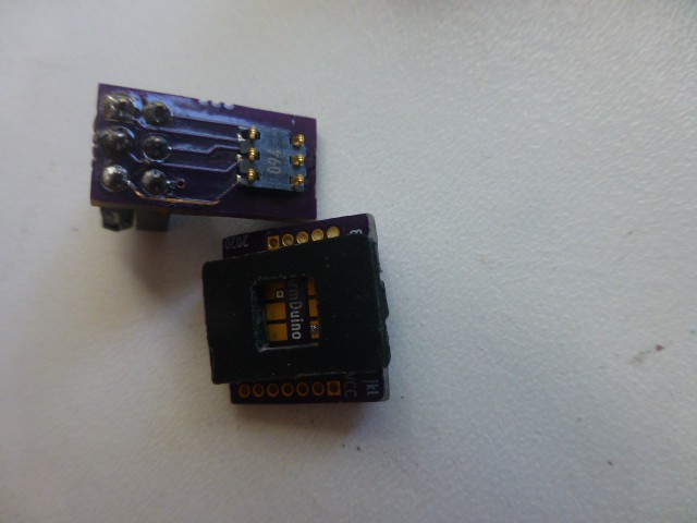
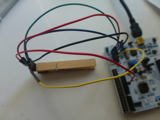
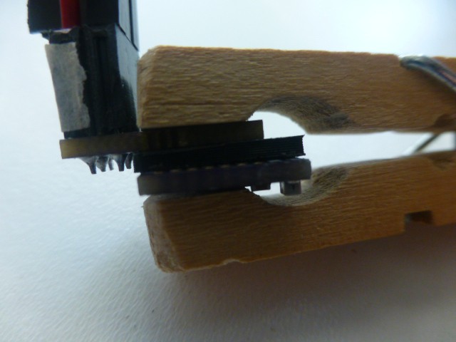
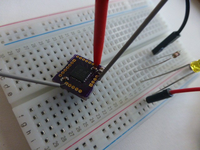
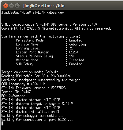
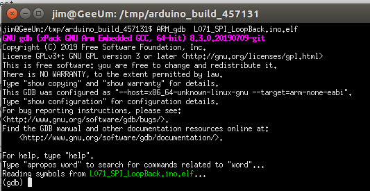
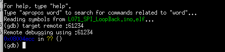
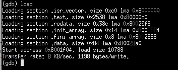
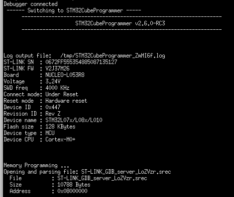
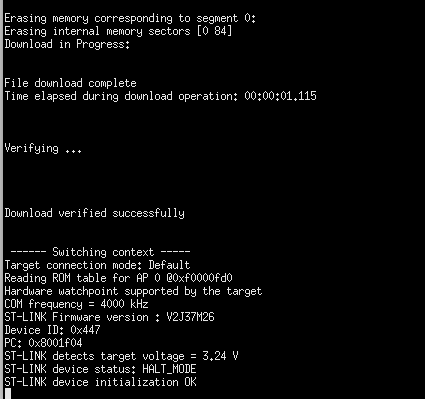
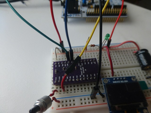
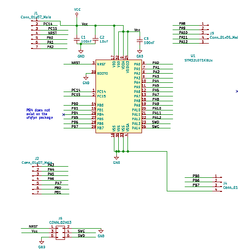
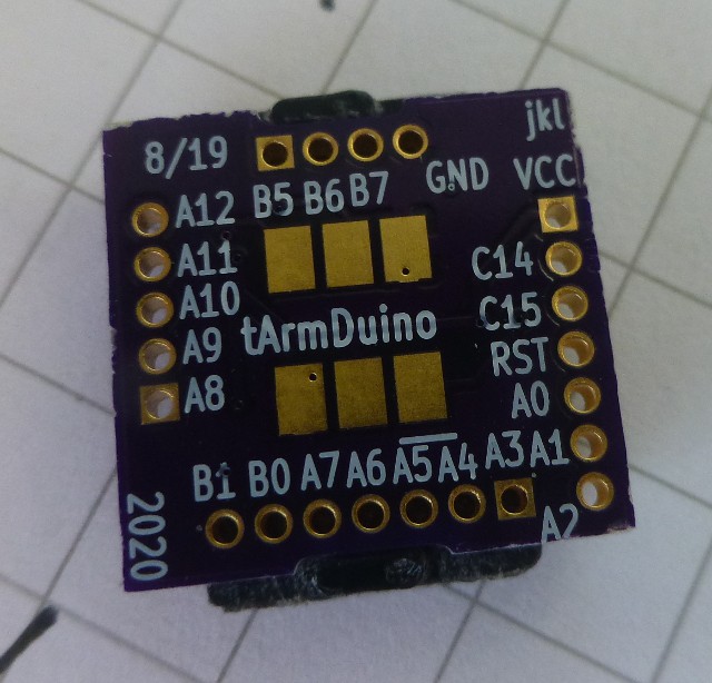
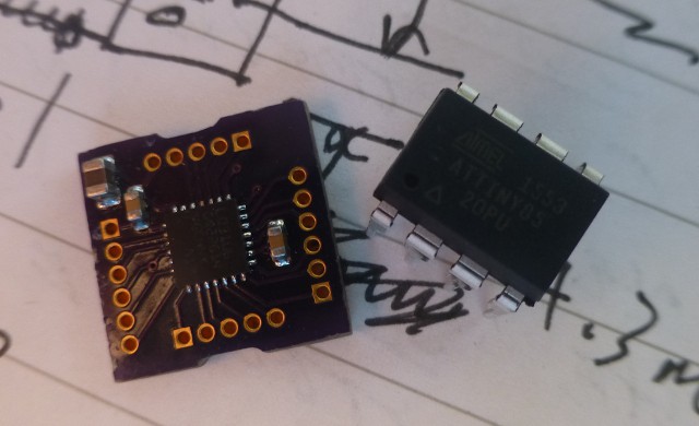
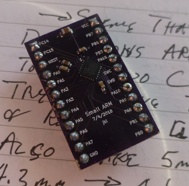
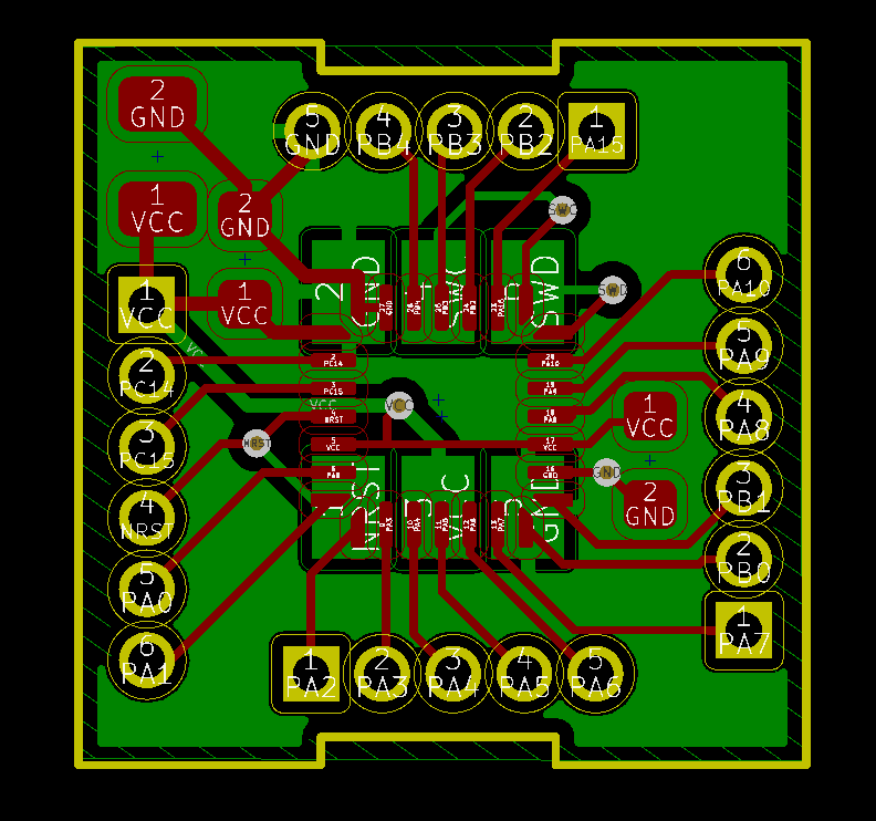
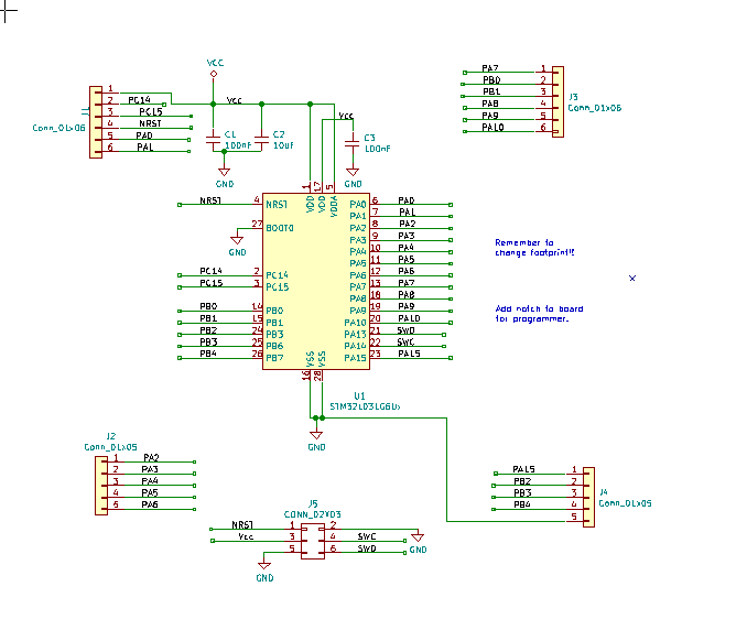
Working in KiCAD and utilizing the debug connector scheme first described in POV programmer, I created the board seen in the picture (the one with parts on it L031G6 version). As mentioned above, this led to the creation of the very similar other design shown (L071KB version). The only parts on the board are the microprocessor and the decoupling capacitors. The reset line is pinned out so a button can be added if desired. Cycling power will also cause a reset. The SWD debug interface goes to the programming footprint. The idea is to provide maximum flexibility so the application can be as small and targeted as desired with no extra baggage. Downloading and debugging is done using the SWD interface. So it's not plug and play like an Arduino or Teensy, but it's not difficult. USB can be added to the serial port, but I typically don't use it for most projects.
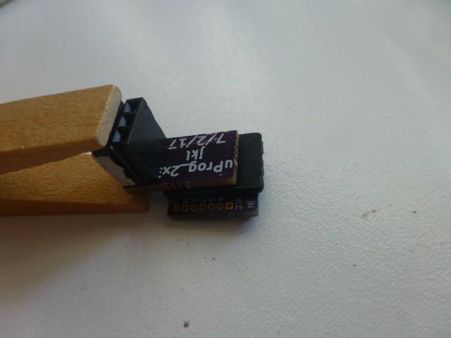
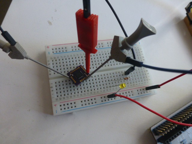
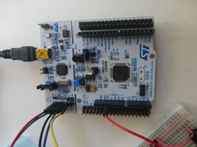
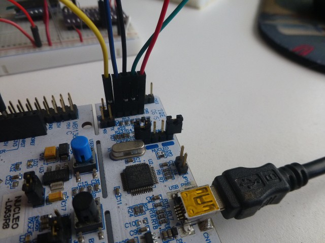
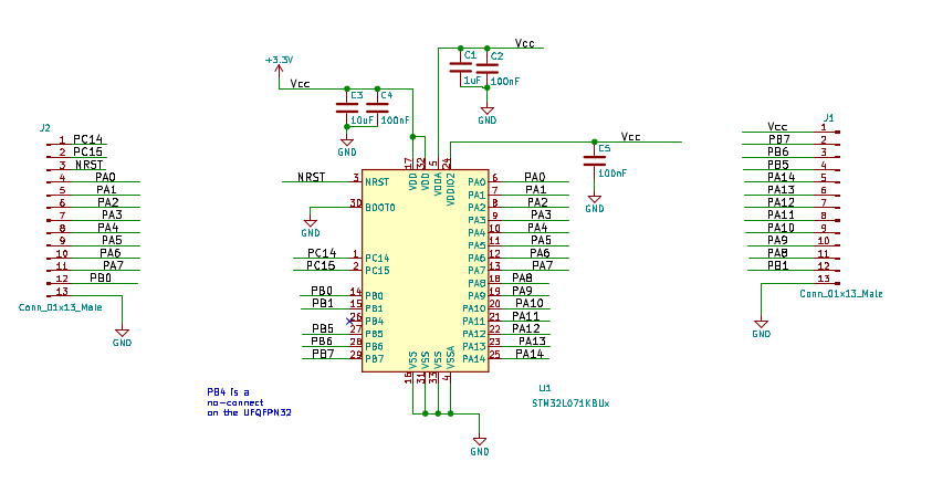
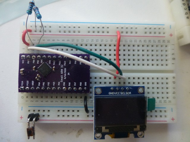
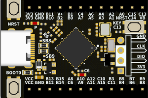
To make prototyping as easy as possible, a bread-board compatible version is necessary. The SWD interface lines are pinned out on the breadboard version so jumpers can be user to program and debug. Not that the tiny version can't be breadboarded, it's just less convenient. The programming header, while very workable, is still harder to connect and may necessitate disconnecting some other pins. Using a breadboard version makes life easier through early stages of development. Once an application is mostly working then it can be moved to the tiny version.
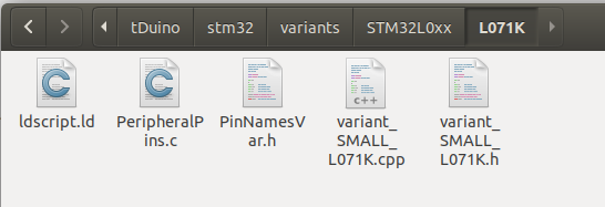
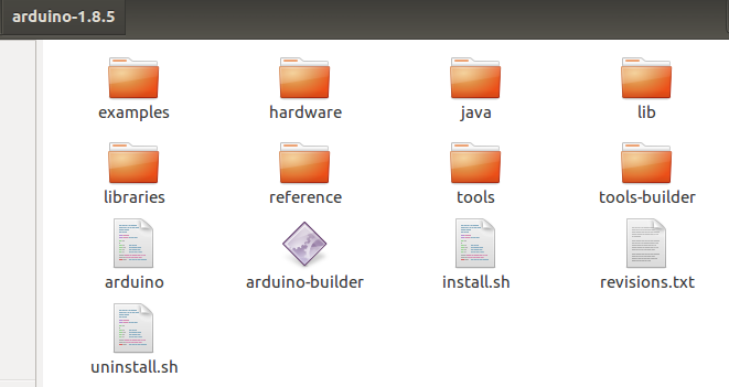
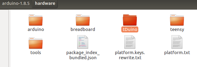
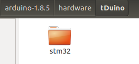
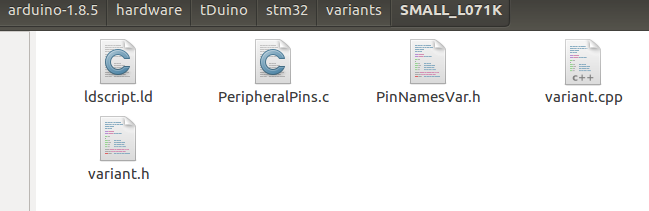
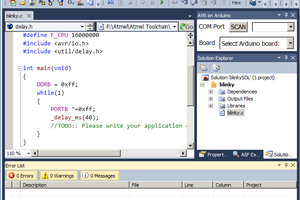
Creating a new Arduino and adding it to the Arduino environment requires several software steps. Without these, even the slickest hardware won't be satisfactory. I'll explain these steps as I go along.


 ZaidPirwani
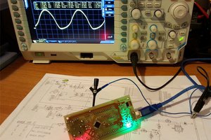
 Just4Fun
 DIY GUY Chris
I'm not sure what you're trying to say or ask. If your concern is what type of power to supply, then the answer is that it's up to you!. You can use a 2032 coin cell if you don't need much power, or a lipo with a stepup/down controller. As with nearly all details of TinyArmduino, you get to make the trade-offs. Read the data sheet to see the power requirements, then configure a suitable system for your needs.