 doctek
After adding the tArmDuino to the Arduino IDE, it is still not possible to program or debug it. The hardware and software tools to do that must be put in place. Programming and debugging tools for tArmDuino are all courtesy of ST. Although it's a large package, I recommend downloading and installing STM32CubeIDE. Since I use other STM devices, I find the Cube IDE useful, although the Arduino IDE is much easier to use for the tArmDuino. I will explain how to configure the programming and debug tools needed based on installing STM32CubeIDE. Although it may be simpler to install STM32CubeProgrammer instead, you still need STM32CubeIDE to get the gdb server. Al Pacini provided most of the hints and details that got my tools working.
The directory ~/STMicroelectronics/STM32Cube/STM32CubeProgrammer/ must be created if it does not exist. This directory was not created when I installed STM32CubeIDE, so I had to do it. If you install STM32CubeProgrammer (as Al Pacini suggests), it may be created for you. On my system (Ubuntu 16.04), the tools I needed were found in /opt/st/stm32cubeide_1.5.0/plugins/com.st.stm32cube.ide.mcu.externaltools.cubeprogrammer.linux64_1.5.0.202011040924/tools. Copy all the folders from that directory to ~/STMicroelectronics/STM32Cube/STM32CubeProgrammer/. When you are done, that directory should contain the folders bin, Data_Base, doc, and lib. Next, go to /opt/st/stm32cubeide_1.5.0/plugins/com.st.stm32cube.ide.mcu.externaltools.stlink-gdb-server.linux64_1.5.0.202011040924/tools/bin and copy all the files in that directory to ~/STMicroelectronics/STM32Cube/STM32CubeProgrammer/bin. From the software tools side, tArmDuino can now be programmed from the Arduino IDE. If you try this yourself, note that the numbers in the file names given may vary, but should be close enough to guide you. I went the step farther and followed Al Pacini's suggestion to create a ~/bin directory and put a couple of scripts in it to make the programming tools easily available from the command line. The udev rules should be in the right place following installation of STM32CubeIDE, so those files are not needed.
To program tArmDuino from Arduino IDE, an ST-Link programmer is needed. The cheapest and easiest way to get one of these that I have found is to buy a suitable Nucleo-64 board. I like the NUCLEO-L053R8 board. Following the manual for it, I remove the jumpers on CN2 (marked ST-LINK) and connect the CN4 (SWD) header to the breadboard version of tArmDuino. Plug the pcb into a breadboard for experimenting. Connect CN4-Pin 1 to the positive rail of the breadboard. This does not power the L071 during programming! 3.3V must be supplied; I use the 3.3V from the Arduiono header on the Nucleo. CN4-Pin 2 goes to SWC, CN4-Pin 3 goes to ground, CN4-Pin 4 goes to SWD, and CN4-Pin 5 goes to NRST. Here's how it looks in a typical setup.
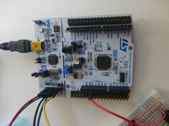
Note 3.3V from Nucleo board to breadboard.
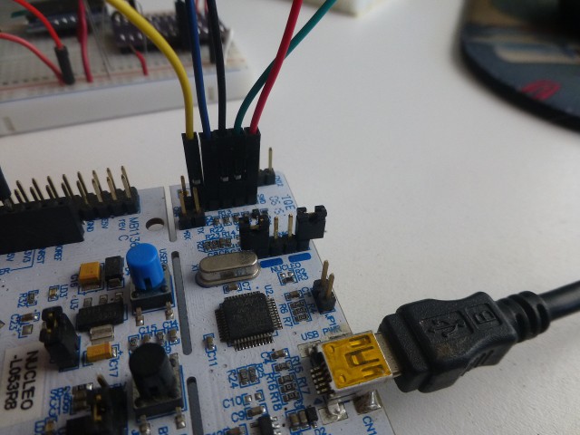
Note colors of wires. The picture below shows them connected to the STM32L071 tArmDuino.
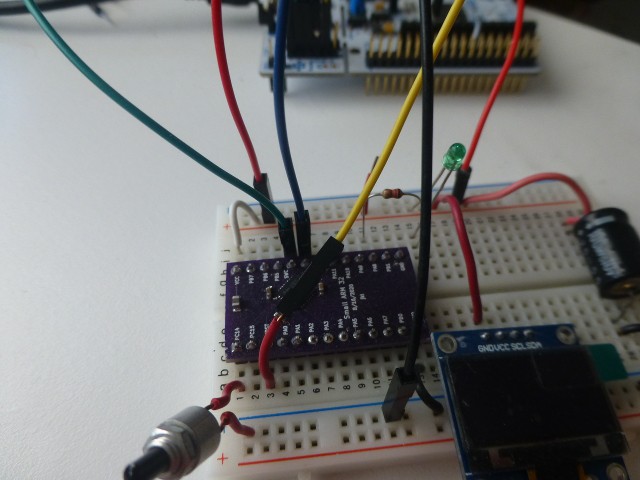
Once the ST-Link is connected, programming is easy. I select Board: tArmDuinoL071, Flash size: 128k, Optimize: smallest, Library: Nano (default), U(S)ART: disabled, and Upload method: Cube Programmer (SWD). I plug in a USB cable to the Nucleo/ST-Link. Then I load the Blink sketch from the Arduino Examples/Basics menu, change the led number to 7, and click verify to be sure it all builds cleanly. Then I click upload to burn it to flash on the tArmDuino. An led must be hooked to Pin PA8 via a resistor to ground or Vcc. Once the sketch is uploaded, the led should be blinking. The variant.h file in SMALL_LO71K has the mapping of Arduino pin numbers to tArmDuino pins named on the pcbs.
While the method just described works great, there are two shortcomings. First, there is no serial port available so the usual printf debugging is out. (The L071K has a UART, but I haven't implemented it.) Second, the powerful gdb (g-debugger) is not supported by the Arduino IDE. The use of gdb will be the subject of another project log.
Let's look at the first shortcoming of the simple method of uploading from Arduino: no serial port is available for printf debugging. I have found a very satisfactory solution to this problem. The tiny SSD1306 OLED display (available from many vendors) uses the I2C bus and can display 8 lines of 21 characters. That's a lot of debug info! Using it is easy. Connect 3.3V to Vcc, gnd to gnd, SCL to PB7 on the tArmDuino breadboard version, and SDA to PB6. (I should mention that the demo sketch from Adafruit for the SSD1306 was my first serious test of using the STM32L071. Since the demo compiled and ran easily, I felt a surge of confidence that using the STM32L071 was a viable idea!) For anyone interested, the sketch L071_ssd1306_MenuDemo.ino is provided. First, get the SDD1306 library (AdaFruit version) using the Arduino Library Manager, load the sketch, verify, then upload. The sketch also assumes a pushbutton to ground on pin PC14. Press the button to start the menu system. Push/release the button to cycle the menu; push/hold for 3 seconds to select. Following this demo, you should find it easy to use the SSD1306 for debugging and display.
Discussions
Become a Hackaday.io Member
Create an account to leave a comment. Already have an account? Log In.