 Enrico Gueli
As described in my last log, I decided to drop the MAX7219 and use the TM1637 LED driver instead. The reason is that it's a lot easier to find 4-digit seven-segment displays with this driver chip all in the same PCB, like this one from Robotdyn.
After having ordered and received of a pair of displays, I started with the software.
Software
I wanted to keep the existing functionality as much as possible, including the support for MAX7219 (you never know if you need it some time later). So before adding TM1637 I refactored the code: I separated the MAX7219-specific code to a C++ class I called Max7219Display, then extracted an interface (i.e. a C++ class with only pure virtual functions) out of it:
struct SevenSegmentDisplay {
    /** Initialize the display */
    virtual void begin() = 0;

    /**
     * Set the brightness from 0 to 255. 0 means off.
     * The display may use less precision.
     */
    virtual void setBrightness(const uint8_t brightness) = 0;

    /**
     * Set the segment data.
     *
     * The array must be 4 bytes long for 4 digits.
     */
    virtual void setSegments(const uint8_t digits[]) = 0;

    void clear() {
        const uint8_t empty[] = {0, 0, 0, 0};
        setSegments(empty);
    }
};
Then I ensured all of the existing code only "knew" about this interface. Once done, it was easy to add support for the TM1637: I made a class called Tm1637Display and added the chip-specific code there. It's the only part of the codebase that talks with the TM1637 library.
Hardware
The TM1637 module requires just four pins: ground, 5V, data I/O (DIO) and clock.
Because I don't have any more free pins in the Wemos D1 Mini, I'll use two of the three pins already used for the MAX7219: SPI MOSI as DIO pin, and SPI SCLK as clock pin.
I don't need to add new components in the schematic, but I don't need to remove any either. In particular the MAX7219 can stay where it is, soldered to my custom-made PCB. Because I'm keeping its LOAD pin tri-state, it will basically never be activated. If I want to replicate the circuit on one of the other PCB copies I have, I won't solder any MAX7219 of course.
I thought about making changes to the PCB. All the audio processing stuff (CPLD, VU meter, JTAG connector) can go away since I won't do any of this (playing around with that was awesome though!). The MAX7219 and the level shifters can now go away too. I could even drop the 3.3V regulator, the one built-in in the WeMos is enough for the only level shifter needed for the IR sensor. So the PCB could become a lot simpler and smaller. But should I really invest time to design a new PCB, order a new batch (while I still have 4 empty PCBs), wait for shipping, just to save some space? So I discarded the idea and kept what I already have, which is more than enough.
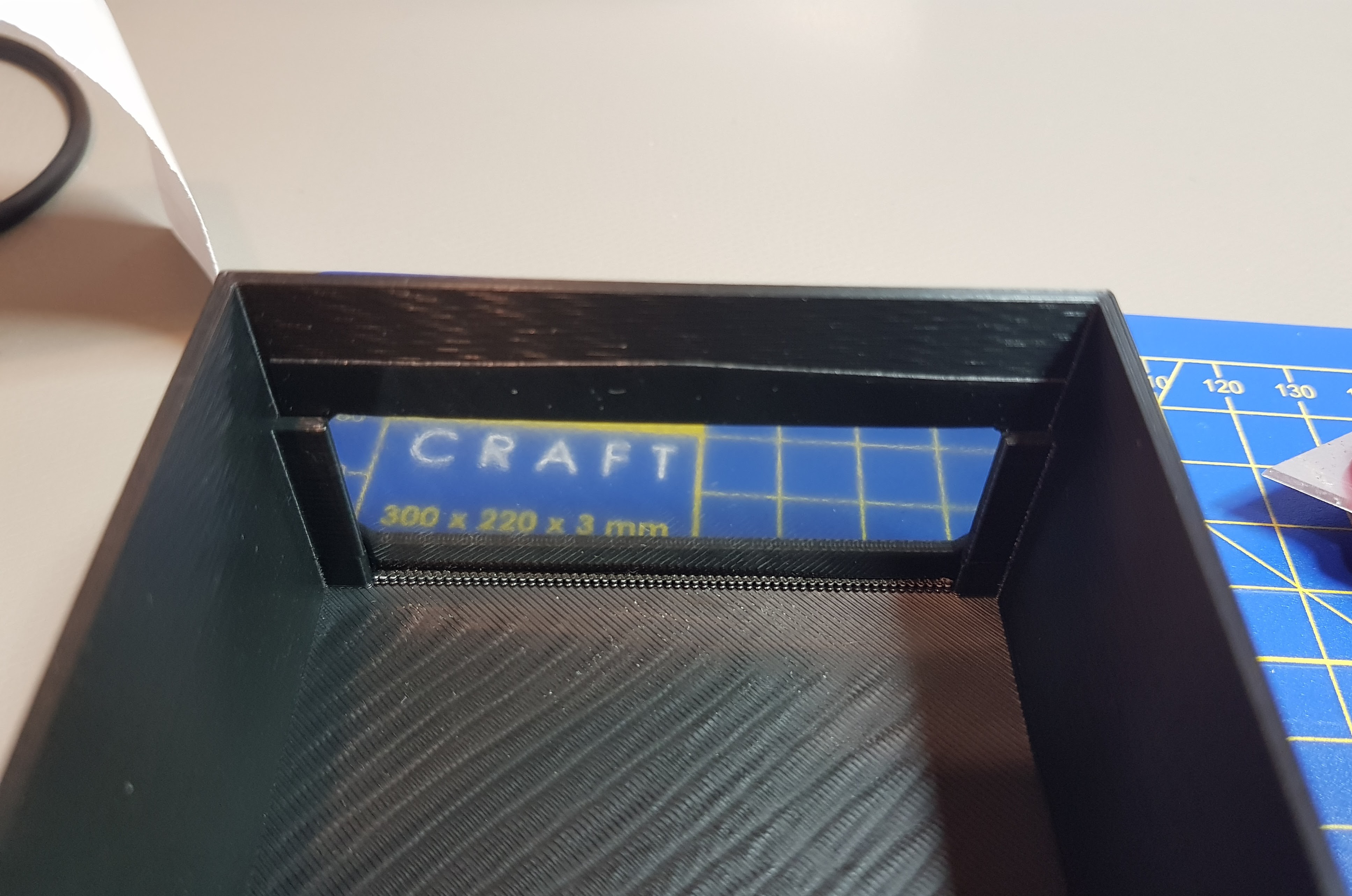
I had to make quite a few changes to the enclosure. The new module is smaller than the old one across all dimensions. I have to move its stand forward. And give room to the four solder pads on the right. I also wanted to use two of the four mounting holes. Here's the result:
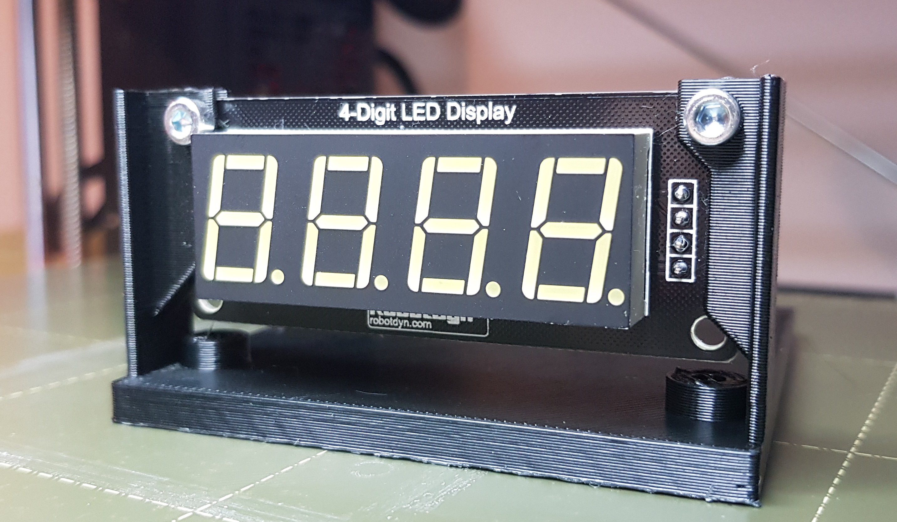
A little desire of mine was to add some kind of color filter, so that the yellowish tint isn't visible while segments are off. It makes the whole thing look more professional too. For this display it was also a necessity, because it gives a very bright white even at low brightness levels!
It was actually quite hard to find a plastic gray filter ~1mm thick of 10x10cm or less. Online art shops didn't have anything like that. Plexiglas was only available from 3mm thick or more. Looking for gray or ND filter only showed expensive photography glass lens filters. It didn't help that I live in the Netherlands and I didn't know the correct search words in Dutch.
In the end I found a shop selling rolls of Oracal 8300 transparent cals with various colors. I found middle gray (#074) quite suitable. After shipping, I realized something pretty obvious: these cals are adhesive, meant to stick to another transparent rigid surface like acrylic or glass. I don't have any of that of course. So I made up for it by carefully sticking two patches of cal together, and trying to not capture air bubbles or dust in between.
I updated the 3D-printed enclosure to also accommodate the filter in front of the display, sliding it from the bottom and fixing it with some tape (not in pic):
Here it is, in its final shape. Really happy of the result:
Discussions
Become a Hackaday.io Member
Create an account to leave a comment. Already have an account? Log In.