 John Duffy
There's a number of features that I want in a meter, but most are not particularly common in existing, commercial meters (which is largely the reason behind starting this project in the first place). The basic requirements I have for this, in no particular order, are:
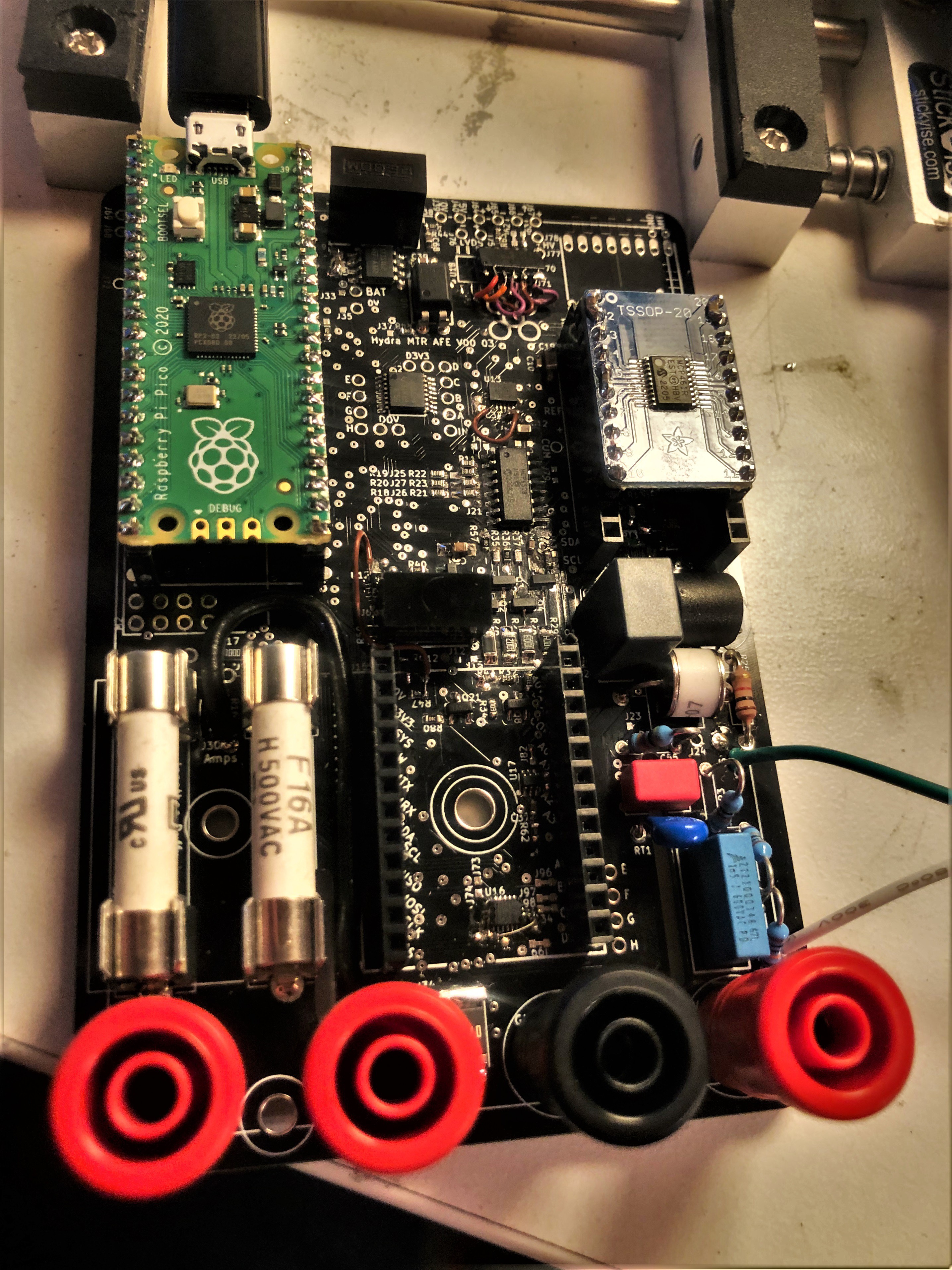
- Isolated USB interface onboard. No weird adapters or anything, just like a normal USB C port. It must have an option to put out serial data in a format which can be copied or logged into something like excel WITHOUT any special drivers or software.
- Option for high sample rate and graphical (waveform) display. Not quite a scope, but it should be capable of looking at basic things like 60Hz power or low-speed digital waveforms.
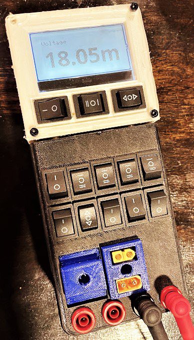
- Graphic (dot matrix) LCD or OLED display, at least 128 x 64 pixels.
- Detachable display, or other wireless option that is NOT bluetooth. I'm not interested in a phone interface.
- Long battery life - 100hr absolute minimum, preference to extend to ~300 if possible.
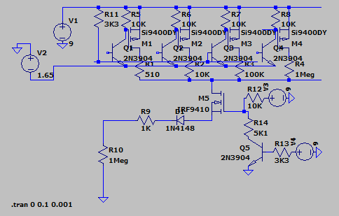
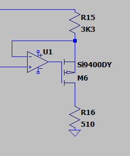
- High diode-test output voltage, at least 3.6V. I often use this function for lighting LEDs to check polarity, so it needs to be able to run white & blue LEDs.
- Simultaneous voltage and current measurement and power calculation. This seems to be becoming more common in commercial meters, but is still absent in most, especially at the low end.
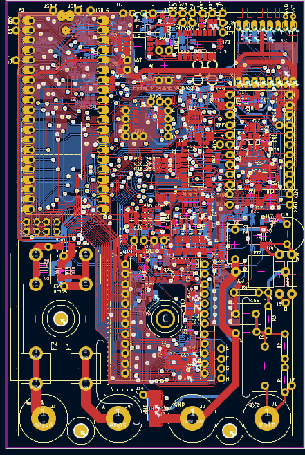
- Designed with future updates/upgrades in mind. Like any first design, this won't be perfect, so it should be possible to modify as little as possible when updating-upgrading the design. To that end, it should be modular at multiple levels.
- Size comparable to commercial meters. It should come in, at most, around the size of a Fluke 87. Any larger will start to be inconvenient.
- It will feel good to hold and operate.
- The fuses will be easy to replace, without disassembling the meter.
- No philips head screws, and all the (main) assembly / disassembly / repair should be possible with just a single size of allen key.
- If rechargeable batteries are used, it should be chargeable over USB
- Fully-exposed interface for main functions. No menus or soft-keys to change AC/DC or ranges or between resistance and continuity or any of that. Just looking at the buttons/switches/dials of the meter should immediately tell me what state it is in. It will also be possible to configure the meter for any "core" function in under 2 seconds. For more advanced things like logging or wireless coms, menus are acceptable.
- Main (banana jack) functions for:
- AC & DC Voltage, from a few mV up to ~250V
- AC & DC Current, from ~10 uA up to 10A
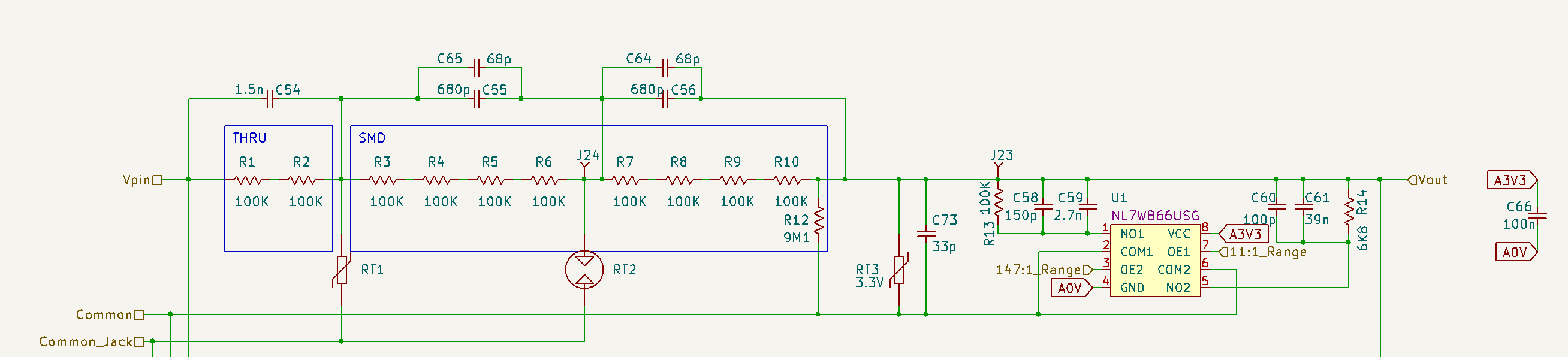
- Resistance / Continuity / Diode test. ~10 ohm to ~1M ohm, diode test >3V
- Power measurement (simultaneous voltage and current, including display of all 3)
- Secondary XT-60 connectors, with independent functions for:
- DC Power from up to 12S battery packs
- DC Voltage, of at least 60V
- DC Current, of at least 30A, but which can tolerate much higher peak current without damage or blowing a fuse.
- Pulse/peak measurement, at mS timescales, for voltage current and power.
These XT-60 connectors are very popular in R/C hobby (drone/plane) batteries, and are increasingly popular for robotics. I use them a ton, and really want to be able to easily measure power through a pair of these. The meter will have one male and one female connector which are connected internally, with current measurement from one to the other. Since this is meant ONLY to be used with batteries and other low-energy circuits, it does not need as much protection as the banana jacks.
There are also a couple notable things that I did NOT set as requirements:
- Does not need to use alkaline batteries,...
Read more »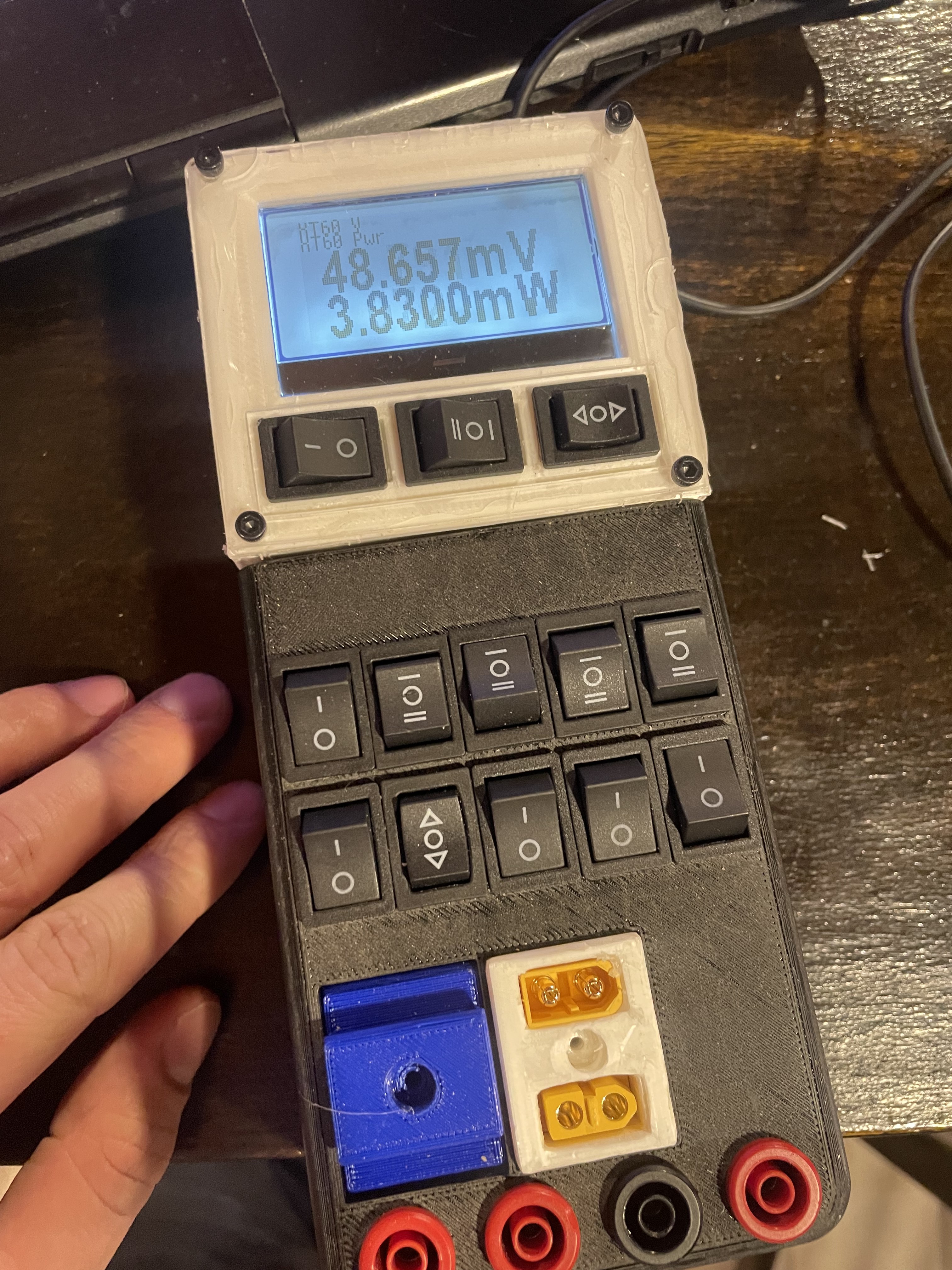
 Karl S
 Jonathan Bruneau
 Paul Andrews
 jbb
jbb