Hardware Unknown
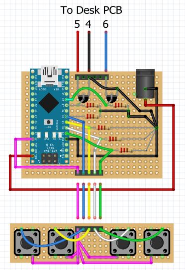
While I could have used an actual schematic, I'm hoping the included Fritzing diagram will help ease the circuit layout process for anyone re-creating this project.
--- Parts I used ---
As an Amazon Associate I earn from qualifying purchases through links in my descriptions and comments. This helps me finance future videos at no additional cost to you. If you choose to support me in this way, thank you.
***All screws, washers, nuts, and standoffs are M2***
***All wire is 22awg solid-core***
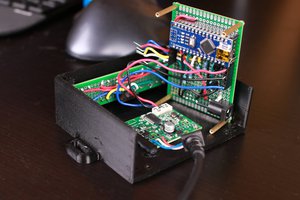
1x Power jacks
2x MOSFETs
4x Buttons
4x Button caps
4x Standoffs

 robives
 mircemk
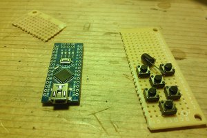
 j0z0r pwn4tr0n