 WJCarpenter
I thought detecting the flame status of the water heater would be pretty simple, but it turned out to have some unexpected characteristics. The burner element and pilot light are enclosed at the bottom of the water heater. There is a small glass window, perhaps 2 inches by 2 inches, through which you can observe the pilot light and the main burner. The purpose of the window is so that you can see if you are successful when lighting the pilot light..
It's kind of interesting how the pilot light and gas flow work. There is no electricity involved, so everything relies on mechanical and thermal interactions. If the pilot light goes out, the gas is completely shut off, including the gas supply to the pilot light itself. To light the pilot light, you hold down a switch which allows a tiny bit of gas to flow to the pilot light fixture. You then push a plunger switch, which I assume is a piezoelectric spark generator. It doesn't always light the pilot light on the first try. Even if it does, you have to continue holding the first switch for several seconds, or the pilot light will go out again. I believe that the pilot light itself warms up some small thermocouple enough to open up the gas supply for the pilot light. When the pilot light goes out, that thermocouple goes cold and cuts off the gas supply to the pilot light. Holding down the first switch bypasses the thermocouple mechanism. The reason to keep holding the first switch down after lighting the pilot light is to give the thermocouple a chance to get heated back up. At least, that's how I believe it works. I am not a lawyer (or a plumber).
Once the pilot light is lit and stabilized, you can turn up the main thermostat. That triggers the main burner to fire, being lit by the pilot light after the gas valve opens. It makes a very satisfying "whoosh!" sound when the main burner ignites.
All of that is very easy to see when you look with your naked eye through that little window.
The first thing I tried was using a common cadmium sulfide (CdS) ambient light sensor. Those cost only a few cents each. They work by providing a variable resistance more or less proportional to the intensity of light striking the sensor. I had a couple of those on hand, including one that was on a convenient break-out board. Unfortunately, nothing I did with the pilot light or the main burner made any difference to any of those CdS sensors I tried. For a while, I thought it was just a problem of getting the active face of the sensor pointed in the right direction. I even bought a few with a larger CdS face, hoping for more sensitivity. After a while, I concluded that they were just being stubborn and didn't want to tell me about the flames I was interested in.
The next thing I tried was a GY-302, which is a breakout board containing a BH1750 illumination sensor (Rohm doesn't make the datasheet available, but retailers make cached copies available). It provides a digital value over I2C, which is very convenient. Alas, it also did not care a whit about differences in the gas flame.
I spent quite a bit of time studying spec sheets for both light sensors and for natural gas flames. I couldn't see why those sensors didn't react at all, but I did see that the most intense part of the natural gas flame is in a frequency range that is not a sweet spot for those sensors. I can't blame the sensors since their job is to detect sunlight or artificial light that is somewhere between white and yellow intended for human eyeball consumption. You can see a little yellow in a natural gas flame, but most of it is blue.
Armed with this half-baked understanding of the light that I wanted to detect, I went in search of a capable sensor. At last I found it: the TSL2591. They are widely available on breakout boards with I2C interfaces from the usual places. I imagine they are all more or less the same, but the exact board that I got was this one:
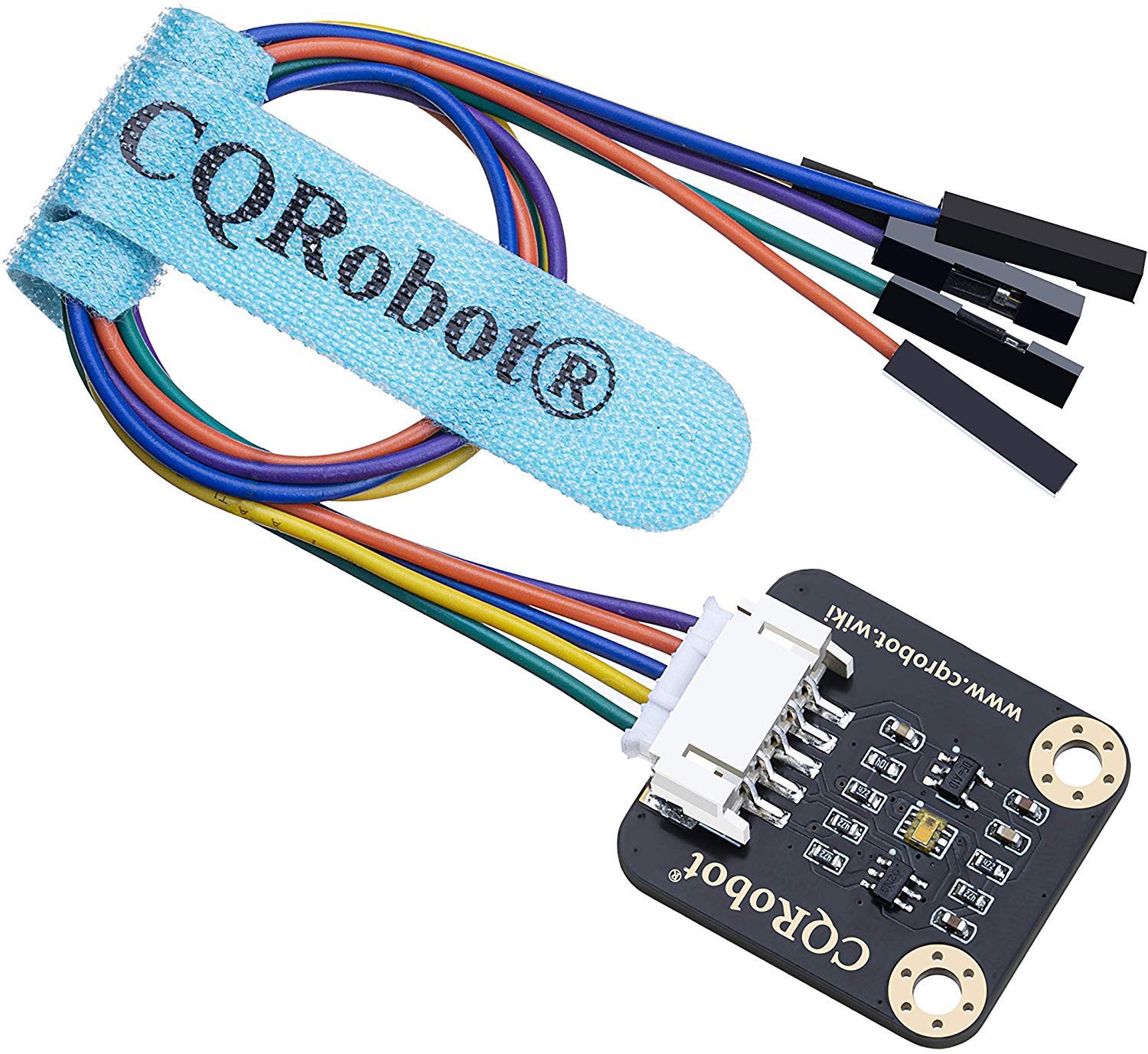
To be honest, I hadn't completely convinced myself that this would do the trick based on my wavelength research, but I took a chance on it. I liked the fact that it advertised a very high dynamic range (600 million to 1). It also contains two distinct light sensors for different (overlapped) frequency ranges. You can use the values from the two sensors individually or as a combination of total light. A quick test showed that it gave a very clear reaction to the gas flame intensity.
ESPhome supports the sister component TSL2561 but does not have built-in support for the TSL2591 . I had tried to track down a TSL2561 to minimize my own hassle, but they seem to be rare. I think it's because they were obsoleted by the manufacturer who recommends against them for new designs.
ESPhome has facilities for using components that it doesn't already know about. A user in this thread https://github.com/esphome/feature-requests/issues/267 had already worked out the details, so it was pretty much a copy-and-paste job for me.
Discussions
Become a Hackaday.io Member
Create an account to leave a comment. Already have an account? Log In.