 Tim Rightnour
I recently had an RO/DI unit fail, which caused problems in my aquarium. I realized that unless I check it daily, I have no idea what is going on in there. This is completely unacceptable. We can automate this.
0%
0%
RO Monitor
Monitor the filters and status of an RO unit.
Become a Hackaday.io member
Already have an account? Log in.
Just one more thing
To make the experience fit your profile, pick a username and tell us what interests you.
Pick an awesome username
hackaday.io/
Your profile's URL: hackaday.io/username. Max 25 alphanumeric characters.
Pick a few interests
Projects that share your interests
People that share your interests


 As shown above, solder in the JST connector.
 If you didn't do headers, solder in the boards. If you did, solder the pins to them, and then insert. For the level shifter, the low voltage side should face the ESP.

 Daren Schwenke
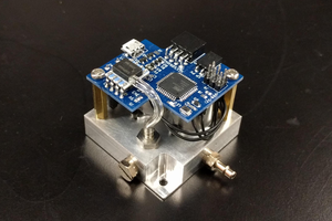
 Craig Watson
 deʃhipu
 Ben Brooks
Can you share the esphome code for esp32 ? please.