I usually like to at least do a header for the ESP, in case it explodes or something and needs to be replaced, or if I want to pull it off and reprogram. You don't need to do all of these unless you are paranoid like me
2
Solder on the JST connector
As shown above, solder in the JST connector.
3
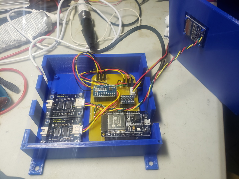
Add the parts
If you didn't do headers, solder in the boards. If you did, solder the pins to them, and then insert. For the level shifter, the low voltage side should face the ESP.
For the TDS sensors, they go on U1, U2 and U3. All of the TDS sensors are optional, you just need to delete the section in the yaml file for the one you don't need. Here I'm just building a 2-TDS setup. The ground goes on the bottom, VDD in the middle, and signal on the top.
4
Add the pressure sensor
First, you need the adapters for the pressure sensor to convert it to RO tubing. Add about 2 wraps of teflon tape to the threads of both, and then screw them all together. We don't want leaks here.Then simply solder the sensor to the board at U4. Same configuration as the TDS, ground on the bottom, VDD in middle, signal on top. In the picture below, the board is upside down.
5
Add the OLED
Solder 4 wires to the OLED:
Now solder those wires to the board. From left to right:
VDD
GND
SCL
SDA
6
Install into 3d printed case
Use 4 M2-6 screws to install the PCB onto the stands (takes a little downward force to get them started) and then 2 M3-6 screws per TDS breakout to install them onto the stands.
Route the cables for the flow sensor and the pressure sensor out the slot in the bottom. The OLED will pressfit onto the little studs on the top, just be careful, they are pretty thin.
Then install the lid with 4 more M3-6 screws Note. I totally installed the lid upside down in this photo. Ha.
7
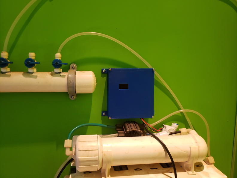
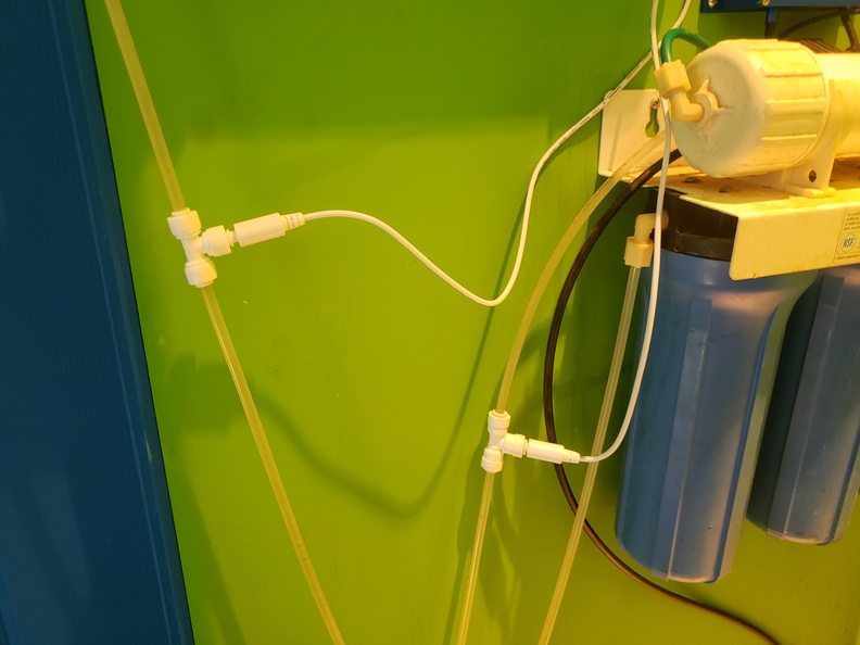
Install onto your RO
Find a good place near the RO to install. Note that the wire for the flow sensor is really short, so unless you extended it, you will want to place the unit based on that sensor. I'm using the flow sensor between the last carbon block and the membrane, to measure the total usage of the blocks.
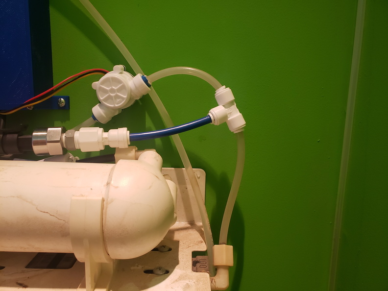
Now cut the tubing between the last block, and the membrane input twice. Add a T fitting and some extra RO tube to connect to the pressure sensor, and then install the flow meter. Note that the flow meter has a flow direction arrow printed on the body.
Now install the TDS meters using a T fitting for each, on whichever outputs you want to measure.
 Tim Rightnour
 As shown above, solder in the JST connector.
 If you didn't do headers, solder in the boards. If you did, solder the pins to them, and then insert. For the level shifter, the low voltage side should face the ESP.
 Then simply solder the sensor to the board at U4. Same configuration as the TDS, ground on the bottom, VDD in middle, signal on top. In the picture below, the board is upside down.


 Route the cables for the flow sensor and the pressure sensor out the slot in the bottom. The OLED will pressfit onto the little studs on the top, just be careful, they are pretty thin.
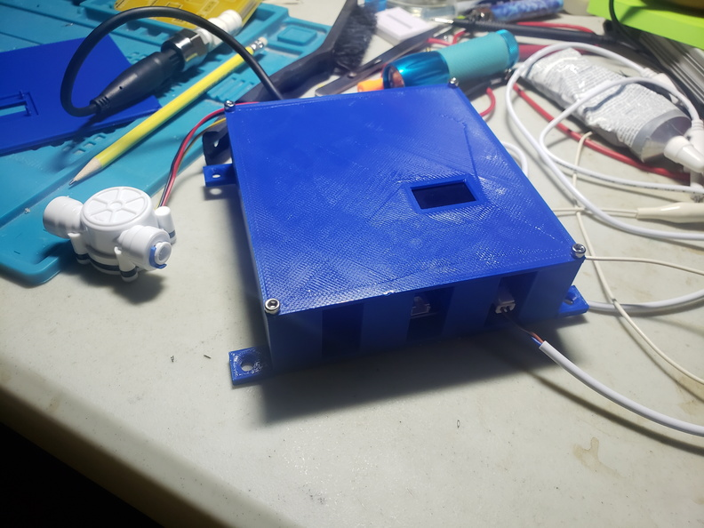
Discussions
Become a Hackaday.io Member
Create an account to leave a comment. Already have an account? Log In.