 Evgeny
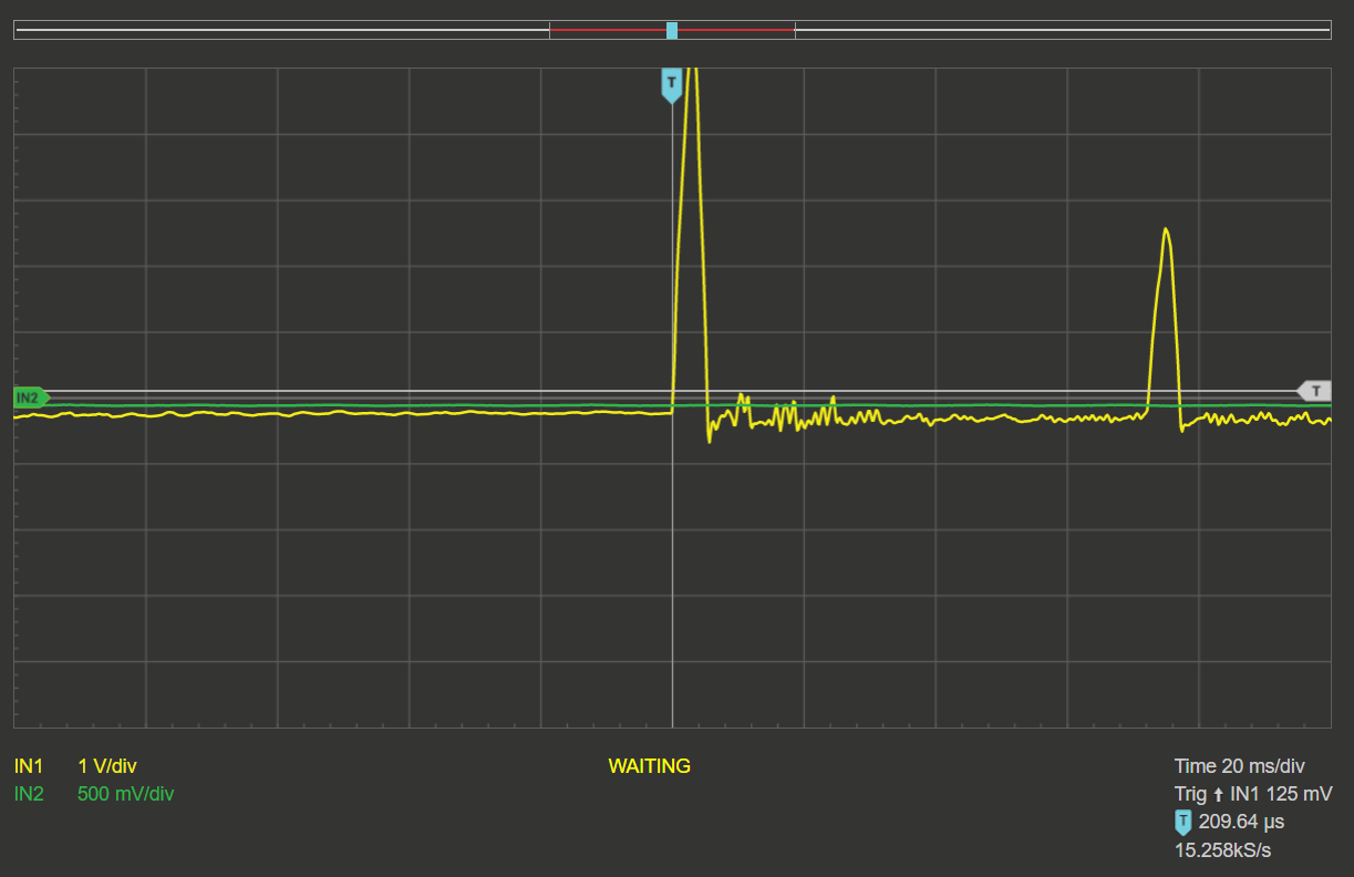
The midi controller - is a STM32 based system with total 18 inputs sampled at 10kHz rate.
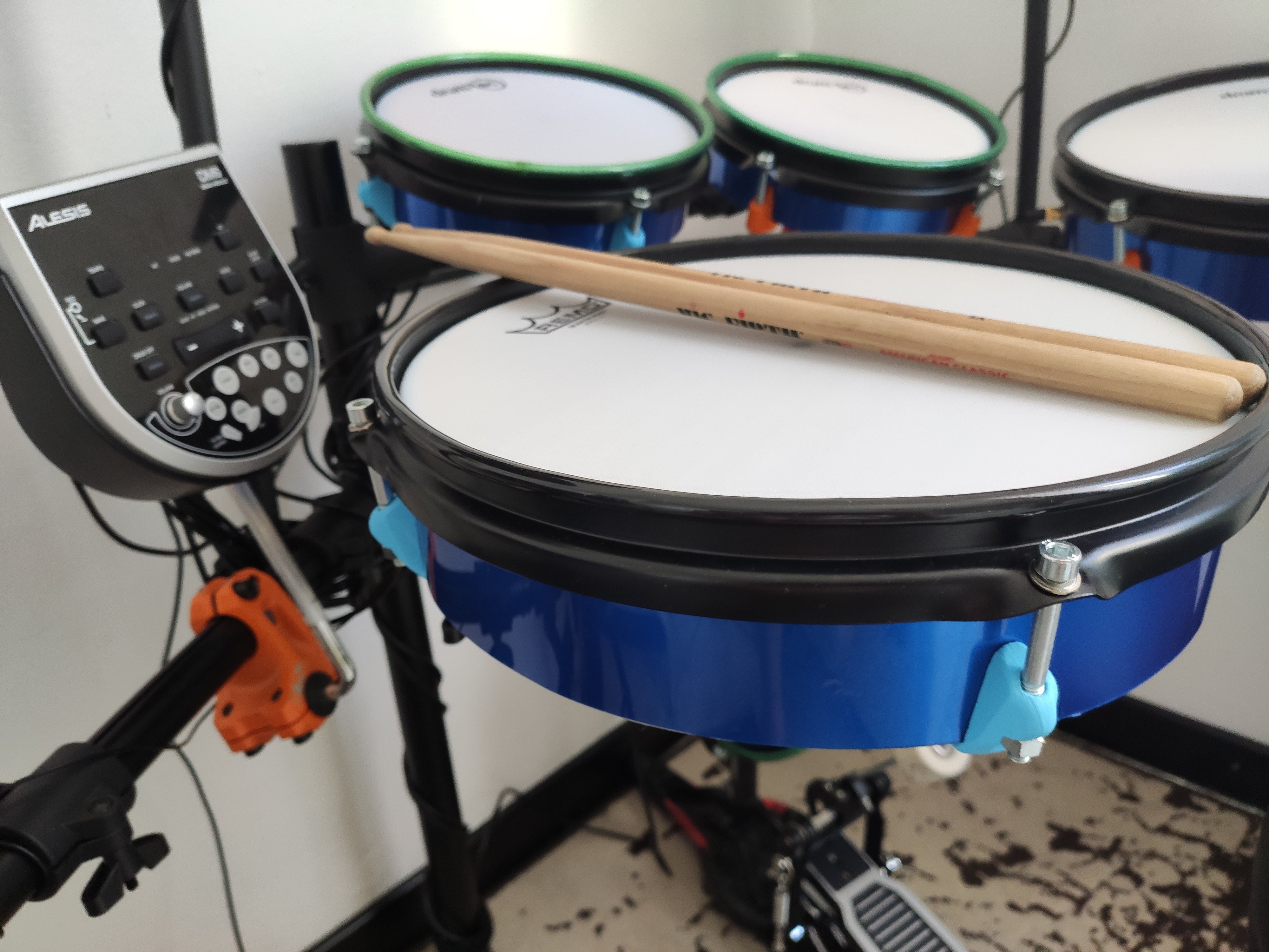
So it is done. Finally manage to put everything together and record small demo.
Phisical description:
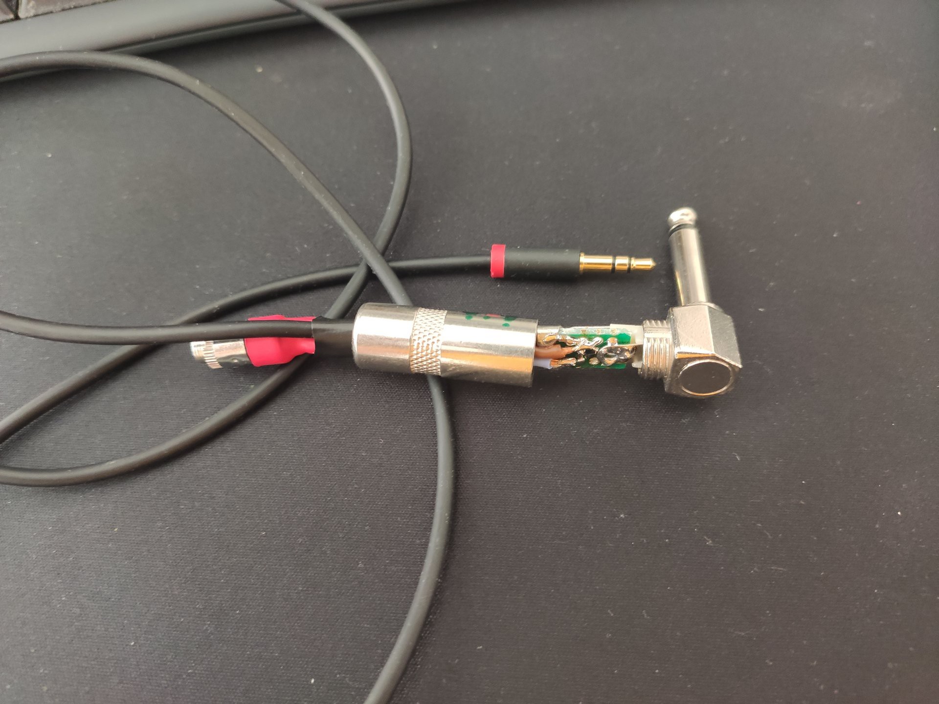
Drumidy main board is a small 60x90mm PCB with a few smd components, 9x stereo jacks, 1 USB port, and place for a STM32 Nucleo G431 board (similar to arduino nano, but faster)
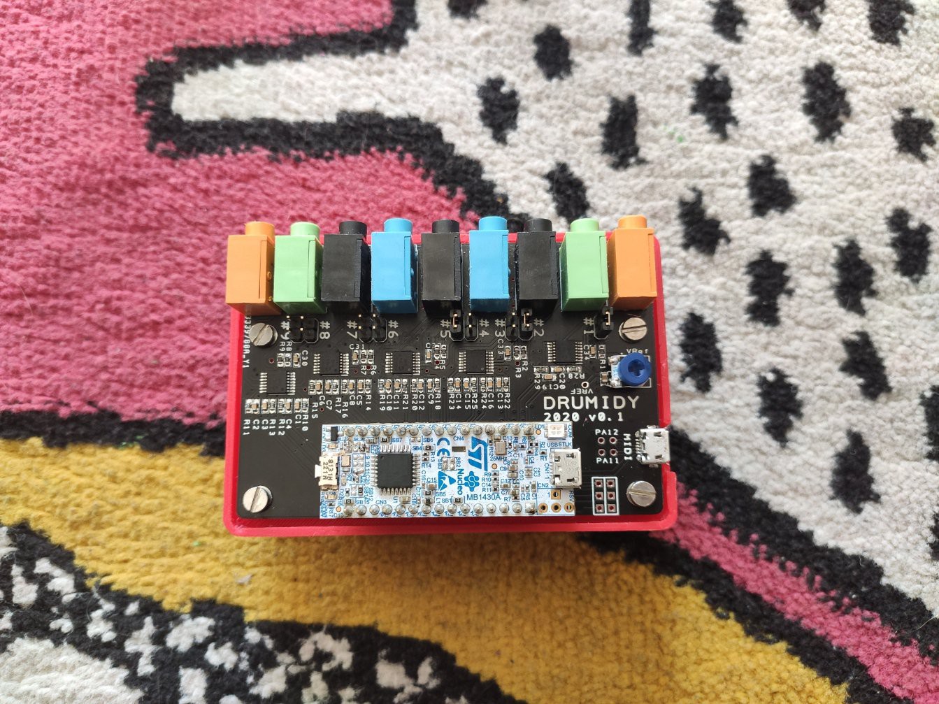
Each stereo jack has two inputs - main (volume sensitive) and auxilary (on/off).
In general, 9 input should cover basic drum set, but to make it more interesting, you could do things like that:
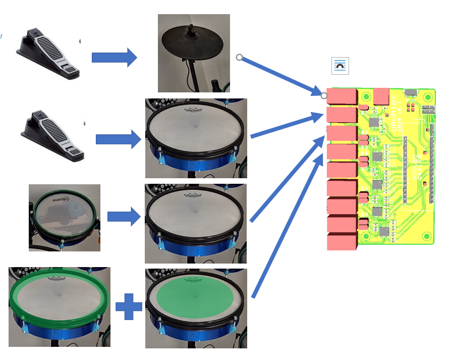
The auxilary channels have optional pull-up resistors. With the resistors disactivated, the channel will be triggered when the level on the input becomes higher certain threshold. To use the channel for a pedal (or button input) you need to activate the pullups.
Electrical description
Source code for the micro: https://github.com/EvgenyD/Drumidy
PCB design and schematics - same link or in the files section.
The system is based on a pretty fast microcontroller in a form of a devboard:
https://www.st.com/en/evaluation-tools/nucleo-g431kb.html
The reason to use it as a devboard is simply to avoid implementing power part on the PCB. As a bonus, it also provides extra USB serial port which I intend to use for debugging and configuration of the drum controller, and drug-and-drop firmware update.
Each channel passes through an opamps (4x4channel opamps). for main channels the opamp provides a buffer (safety measure), for the auxilary channels - opamp sets the threshold for the trigger (1 trimmer to rule them all).
Software part
When plugged into a PC, the board is recognized as a typical Midi device can be used in any software with midi support.
Personally, I use sforzando with free sound samples SM Drums.
In order to get lower latency on windows PC, I use ASIO2ALL or Magix LowLatency drivers. (the magix's one come with the MusicMaker software but works with sforzando as well)
This combination works "out of the box" and require no adjustment. I only had to adjust volumes for the different voices.

 ThunderSqueak
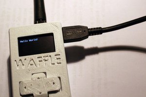
 M.daSilva
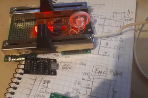
 PjotrA@aliendnatronics
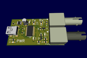
 James
James
I actually have done that, I'm just to lazy to post this stuff.