 Jan Mrázek
RB0004 - Neopixel Booster
Probably all of us makers love WS2812B - the addressable LEDs, which are often
called "Neopixel" based on the brand created by Adafruit. They are so
much fun to play with! Especially when you can buy them in strips for less than
18 USD/5 meters!
These LEDs are, however, power-hungry, and the strips are not the best design.
Therefore you often struggle to power them - you need a 5V power supply with
a large current rating. And these aren't easy to get. And if you get one, the
strips behave weirdly - the end of the strip has more reddish colors compared
to it's beginning.
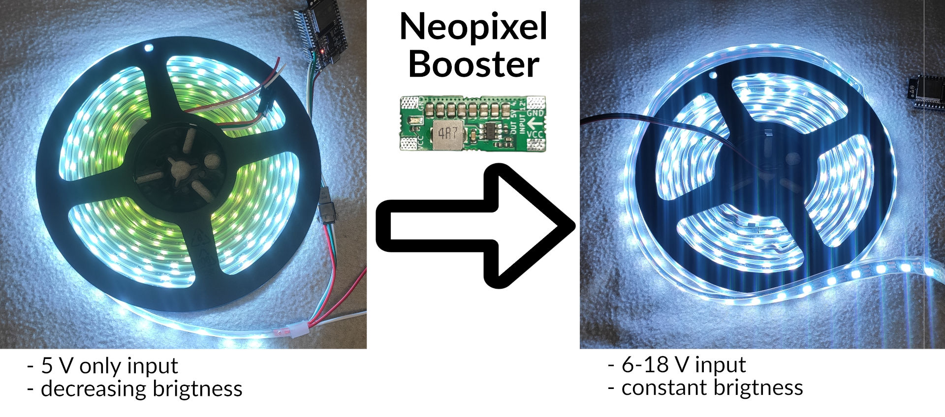
This is where RB0004 - Neopixel Booster comes in: it solves all the problems
above.
View this project on .CADLAB.io.
The Problem In Short
If you are interested in a much in-depth explanation of the problem with some
measurements, see the page about strips properties.
Each of the LEDs consumes around 60-70 mA in the full brightness (based on the
temperature and batch you have). Therefore, if you have 300 LEDs in a strip,
they will consume 18-21 A! That's a lot of current. When you push current
through a wire, there is a voltage drop according to Ohm'slaw. The copper wire on the strips
is relatively thin and narrow. Therefore, there will be a significant voltage
drop. It is quite common that you supply your strip with 5 V, but you will
measure only 2.5 V at the end of the strip. That means your LEDs can't shine the
full brightness.
But why they turn red? There is a red, green, and blue LED in the
chip. Each of the LED colors has a different forward voltagedrop - the blue one has the larges
one, and it is usually around 3 V. That means if the LED is supplied with less
than 3V, it cannot light up the blue channel, and thus, it is missing from the
final color.
You could solve that by just bonding a thick wire to the back of the strip.
However, a suitable wire for 21 A will be pretty thick (around 3.5 mm²).
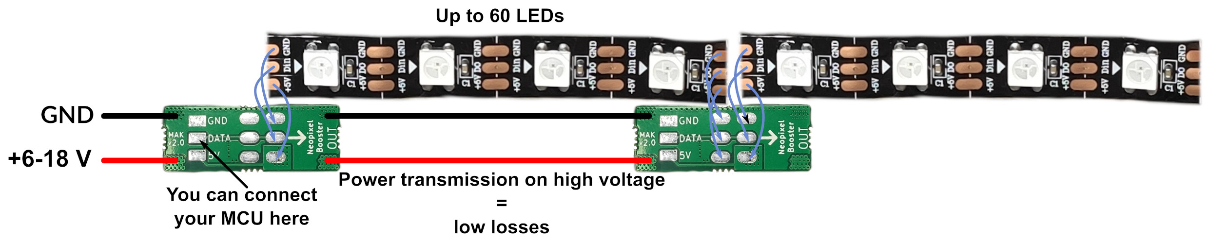
Therefore, it is better to power the whole strip with higher voltage, thus
lower the current flowing in the wires and only lower the voltage locally for a
few LEDs. And that's what exactly Neopixel Booster does.
You run an extra wire around your LED strip and connect multiple Neopixel
Boosters in the strip to power it by segments:
Features
- fixes the powering issue of the WS2812B LED strips on the market
- you can power your strips with 6-18 V - higher voltage allows you to use thinner wires - when your power your strip with higher voltage, the power supply can have a lower current rating. - you can easily use a PC power supply for powering your LEDs. - you can easily power your strip from 2-4 Li-ion cells connected in series
- requires relatively easy modification of the strip, see the assembly guide.
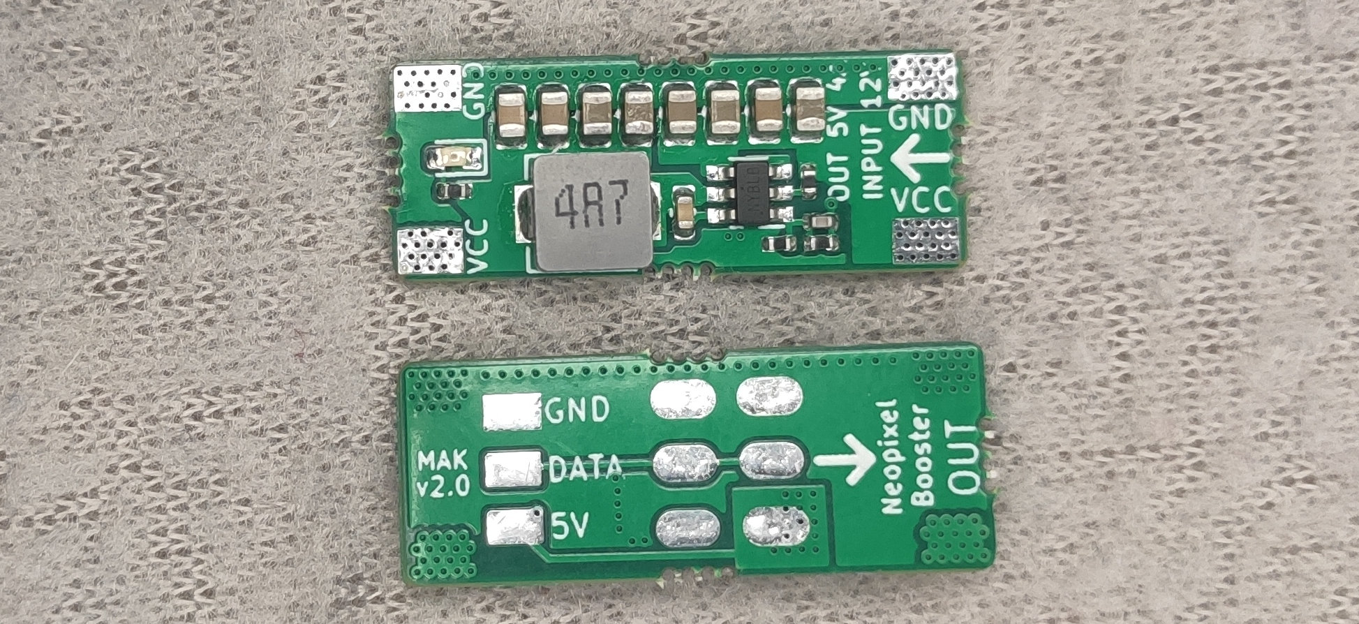
- Neopixel Booster is step-down module; see its characteristics and performance.
I Want One!
You can get one from Tindie
How Do I Use Them?
Once you buy a kit from us, follow the assembly guide, and
within an hour, you can have your boosted strips.
How Many Do I Need Them?
We recommend not to exceed 60 LEDs per one Neopixel Booster. It is best for
convenient assembly to put one Neopixel Booster for each 50 cm of the strip, but
if you want to go cheap, it is OK to apply it every meter.

 Ken Yap
 Christoph Tack
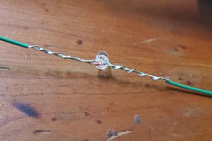
 Martin
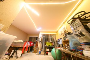
 lion mclionhead
I am new to Hobby electronics and made an addressable display that ultimately failed due to power issues. Some questions, I have read to put a capacitor at VCC to control abrupt changes in current. Do I use one at each module? Before or after the module? So if im using 300 leds I could use 6 modules. Without the module Id need 5 volts 18 amps, I think but if I go to 12 volts is it 4.5 amps? im so clueless with math and OHMS law.