Subhajit
Circuit Diagram of the ESP32 Project
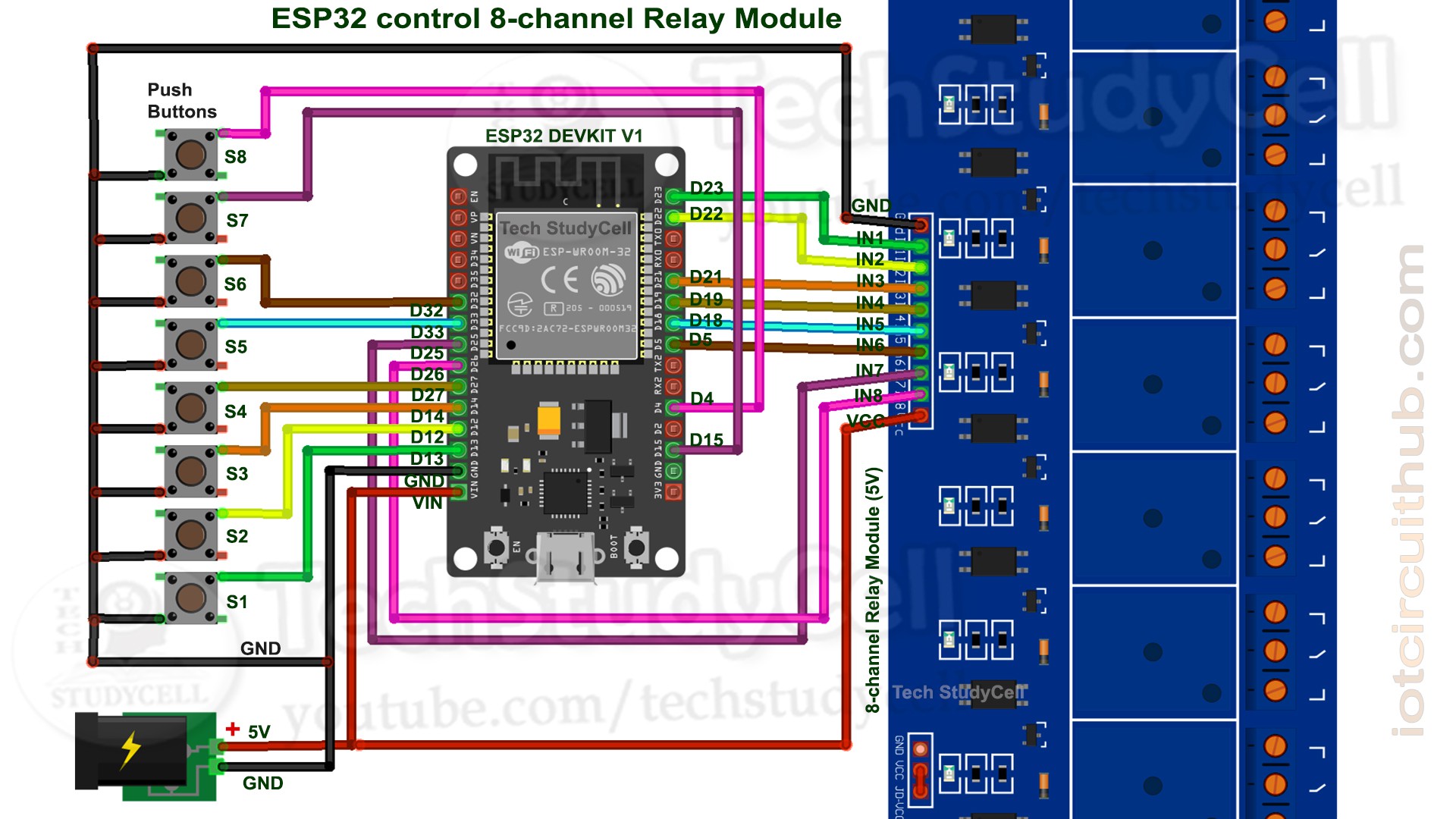
This is the complete circuit diagram for this home automation project. I have explained the circuit in the tutorial video.
The circuit is very simple, I have used the GPIO pins D23, D22, D21, D19, D18, D5, D25 & D26 to control the 8 relays.
And the GPIO pins D13, D12, D14, D27, D33, D32, D15 & D4 connected with push buttons to control the 8 relays manually.
I have used the INPUT_PULLUP function in Arduino IDE instead of using the pull-up resistors.
I have used a 5V mobile charger to supply the smart relay module.
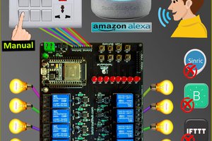
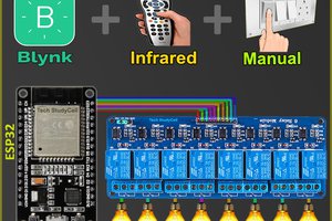
Control Relays With Internet Using Blynk
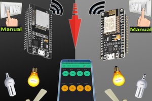
If the ESP32 module is connected with the WiFi, then you can control the home appliances from Blynk App and push-buttons.
You can control, monitor the real-time status of the relays from anywhere in the world with the Blynk App.
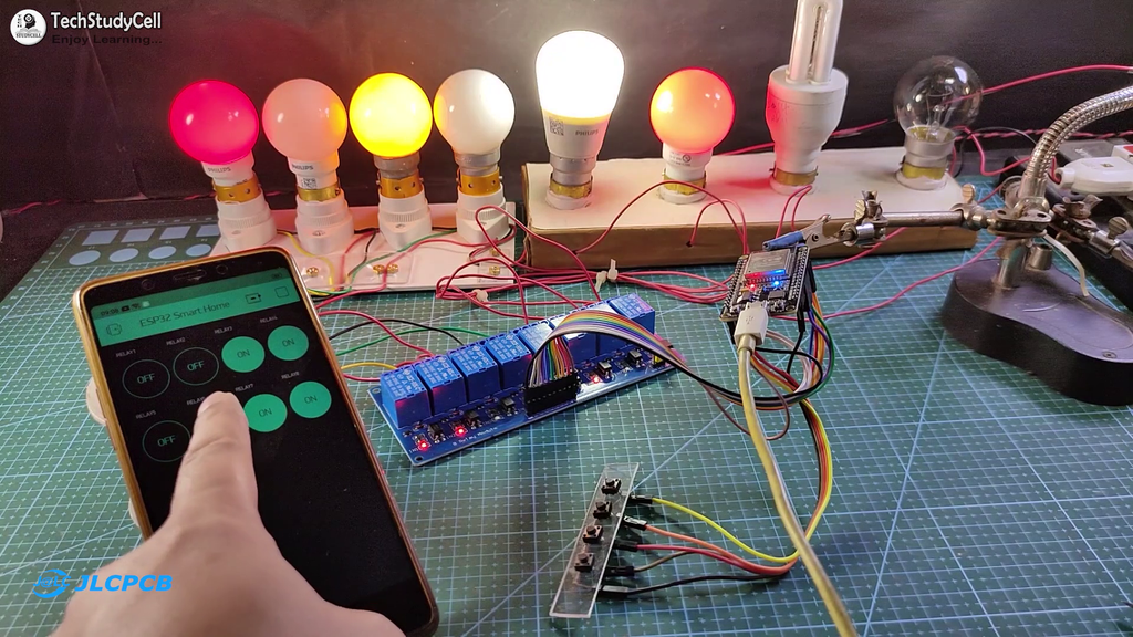
Control Relays Without Internet Using Push-buttons

If the WiFi is not available, you can control the relays from the pushbuttons.
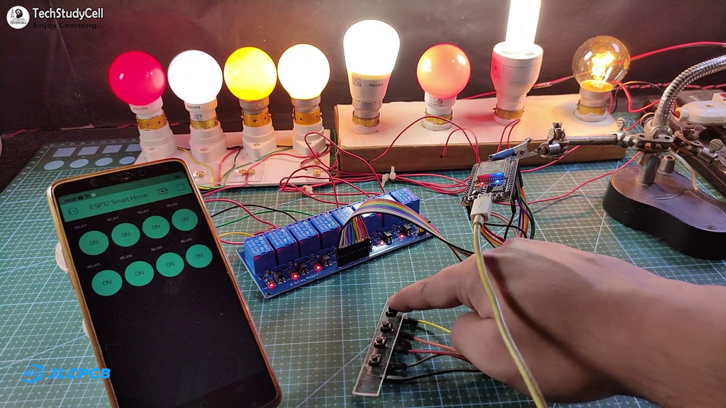
The ESP32 will check for the WiFi after every 3 seconds. When the WiFi is available, the ESP32 will automatically connect with the WiFi.
Configure the Blynk App for the ESP32
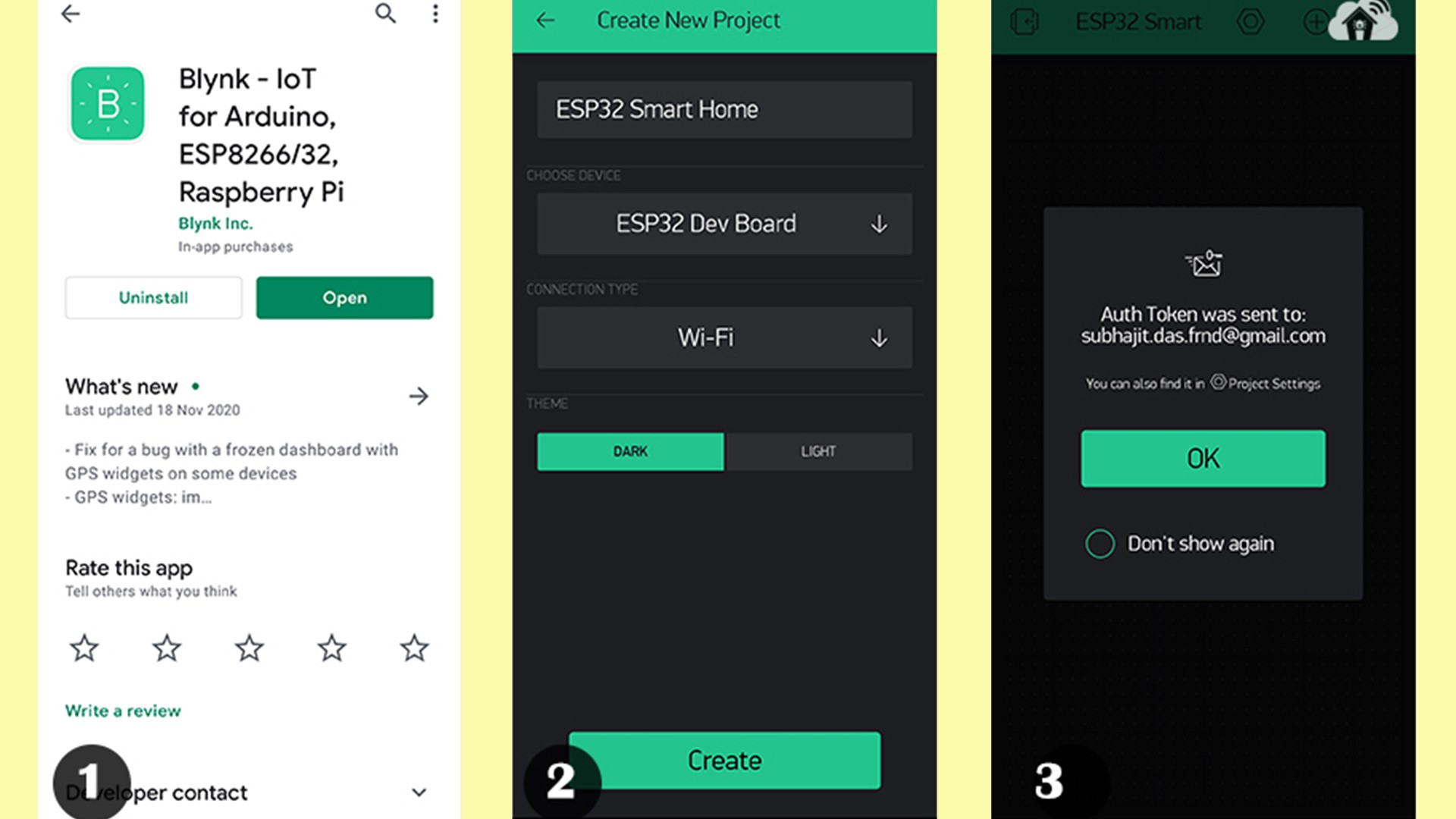
1. Install the Blynk App from the Google play store or App store. Then create an account and tap on the New Project.
2. Give the name to the project, select ESP32 Dev Board, Connection type will be WiFi. Then tap on Create.
3. Blynk will send an authentication token to the registered email id. Tap on OK.
Add the Button Widgets in Blynk App

Then add 8 button widgets to control the 8 relays. Here I have used virtual pins V1, V2, V3, V4, V5, V6, V7, V8 for 8 buttons. And mode will be Switch.
I have explained all the details in the tutorial video.
Code for Blynk ESP32 Home Automation

In the Tutorial video, I have explained all the steps to program the ESP32 DEV KIT V1 using Arduino IDE.
Before uploading the code you have to install the ESP32 board and Blynk library.
Then enter the WiFi name, WiFi password & Blynk Auth Token in the code.
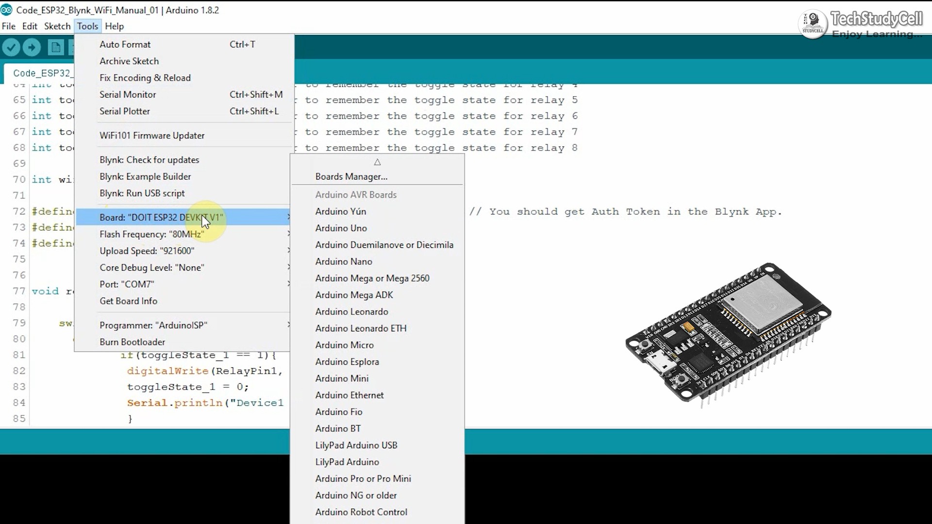
Select the DOIT ESP32 DEVKIT V1 board and proper PORT.
Then upload the code to ESP32 Board.

Program the ESP32 With Arduino IDE

While uploading the code to ESP32, if you see the "Connecting....___" text, then press the BOOT button of the ESP32.
Designing the PCB

To make the circuit compact and give a professional look, I have designed the PCB after testing all the features of the smart relay module on the breadboard.
You can download the PCB Gerber file of this home automation project from the following link:
https://drive.google.com/uc?export=download&id=1Y8rXnczq6baxAKOrBEE8aro-uqcK0J93
Order the PCB
After downloading the Garber file you can easily order the PCB
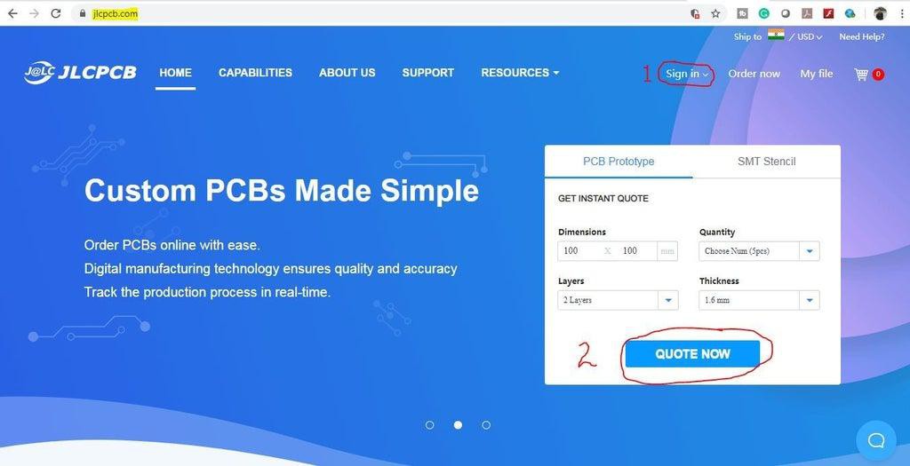
1. Visit https://jlcpcb.com and Sign in / Sign up
2. Click on the QUOTE NOW button.
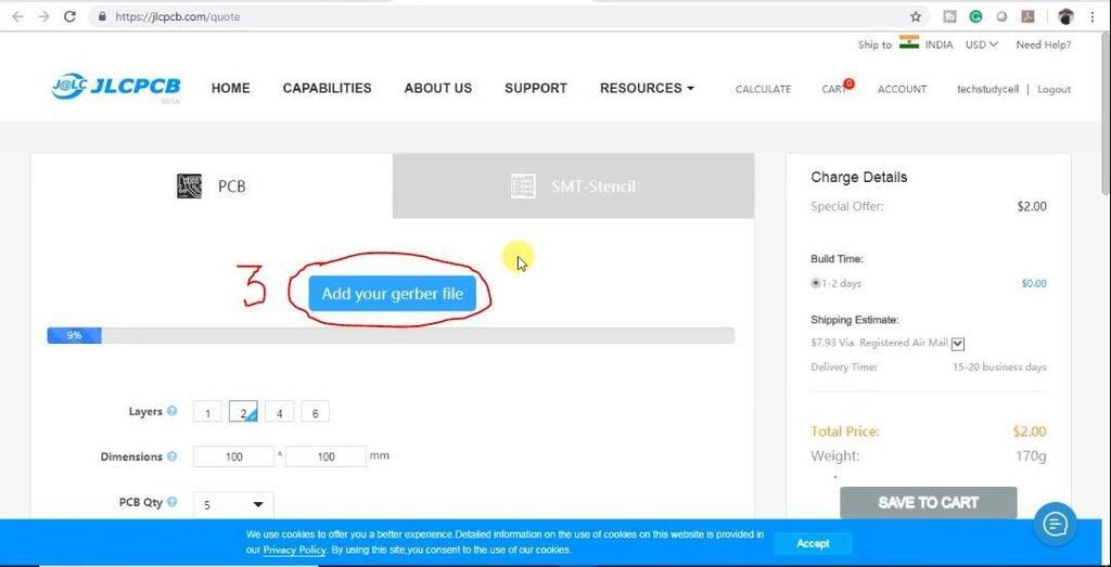
3. Click on the "Add your Gerber file" button. Then browse and select the Gerber file you have downloaded.
Uploading the Gerber File and Set the Parameters

4. Set the required parameter like Quantity, PCB masking colour, etc.
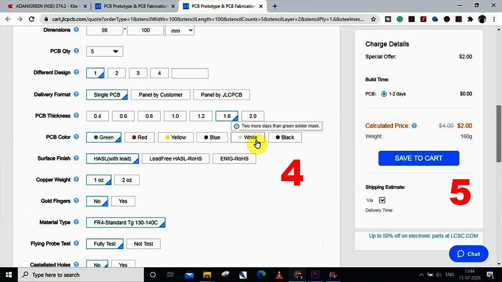
5. After selecting all the Parameters for PCB click on SAVE TO CART button.
Select Shipping Address and Payment Mode
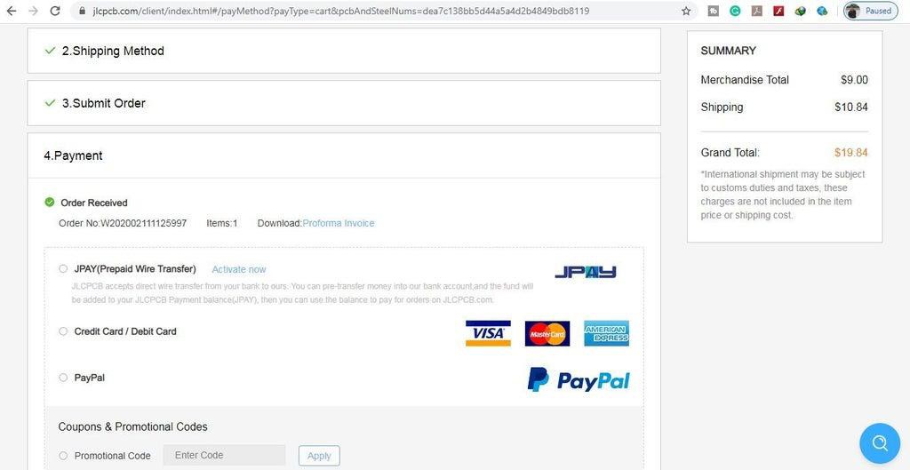
6. Type the Shipping Address.
7. Select the Shipping Method suitable for you.
8. Submit the order and proceed for the payment.
You can also track your order from the JLCPCB.com.
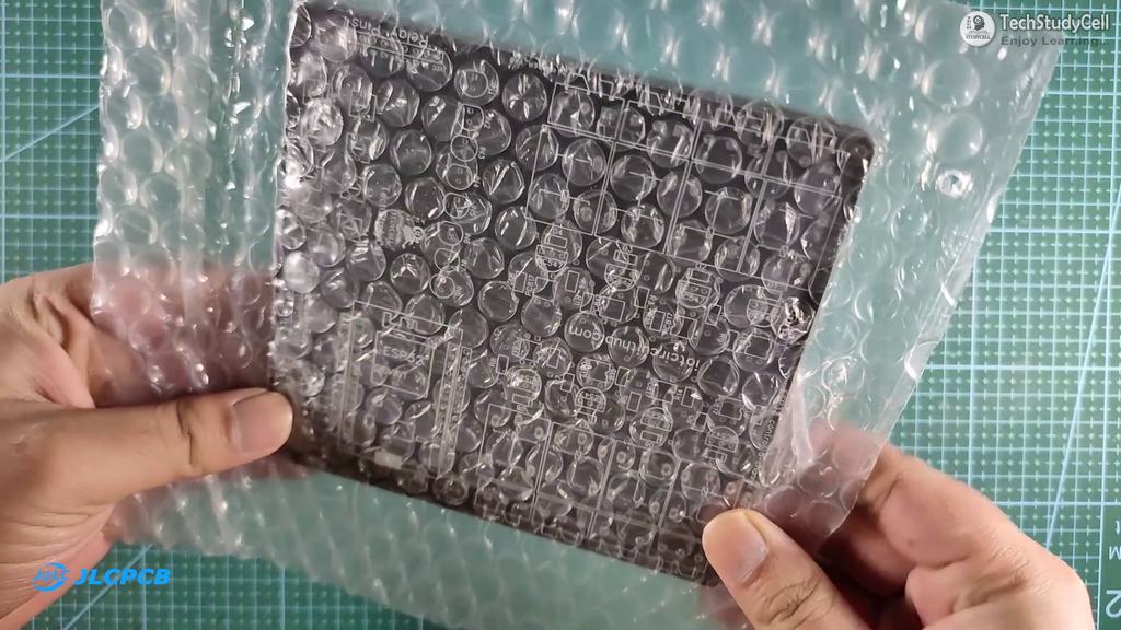
My PCBs took 2 days to get manufactured and arrived within a week using the DHL delivery option. PCBs were well packed and the quality was really good at this affordable price.
Solder All the Components on PCB

After that, I have soldered all the components as per the circuit diagram.
Then connect the ESP32 board with PCB.
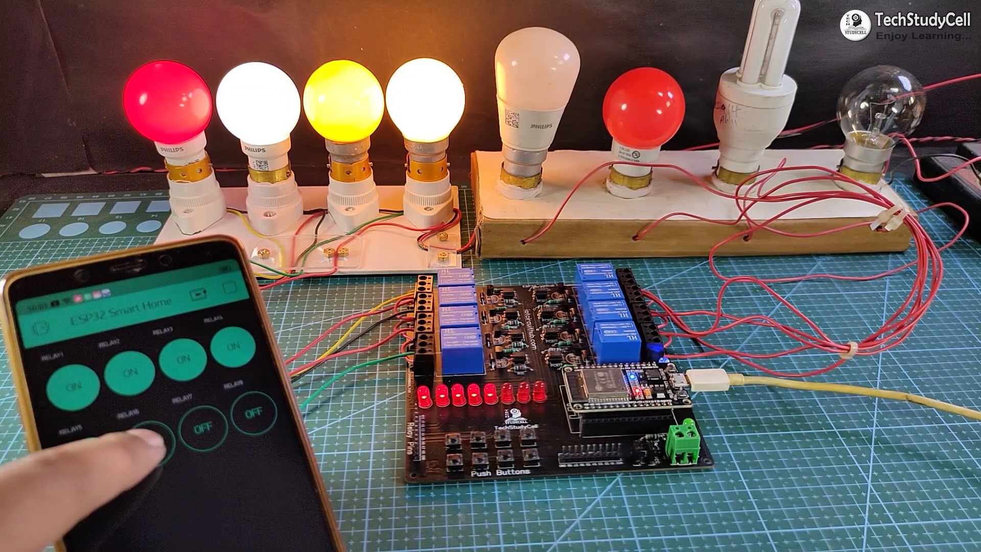
Testing the ESP32 Home Automation Circuit
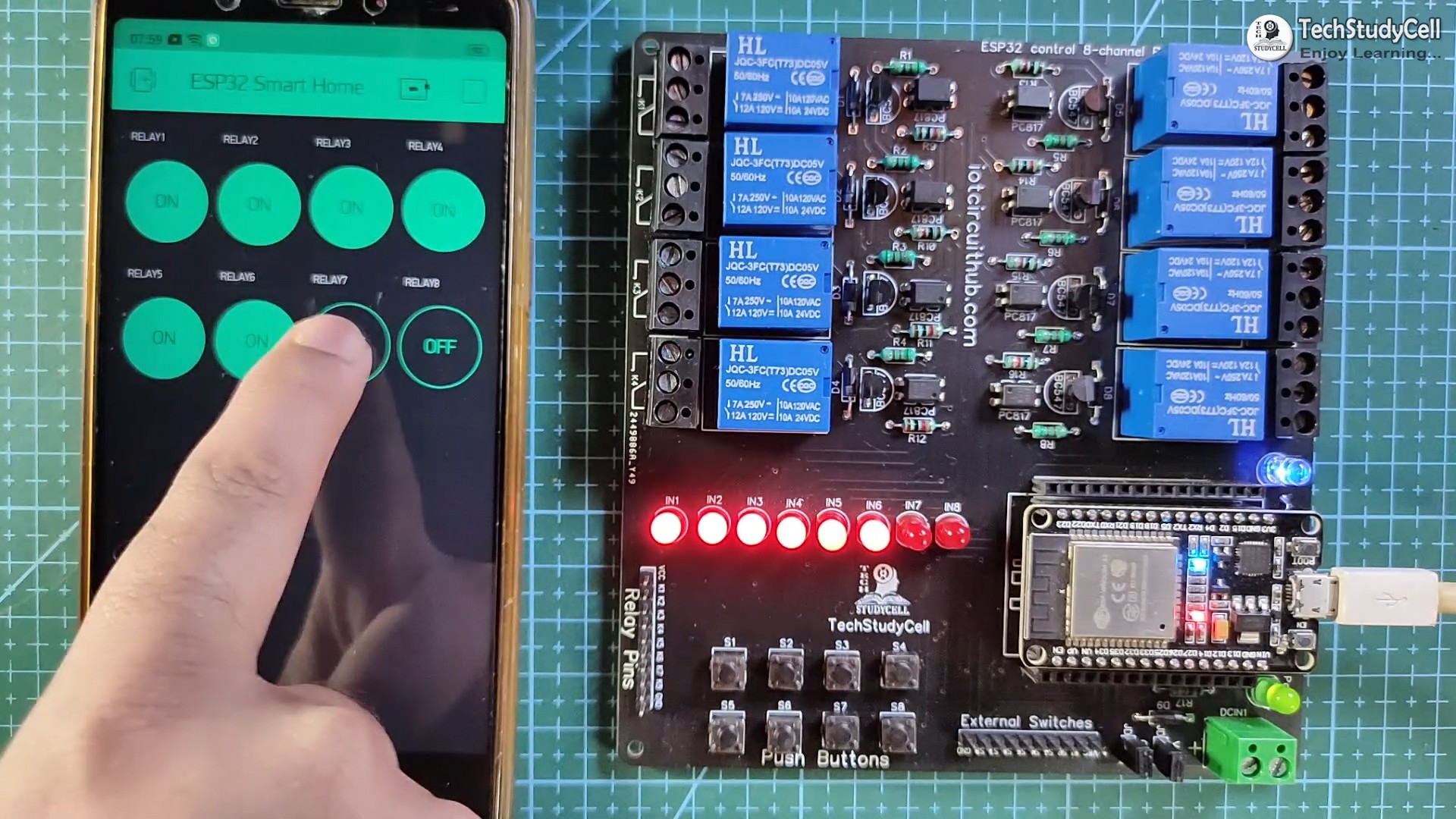
After uploading the code, if the ESP32 connects with the WiFi, the blue LED will turn on.
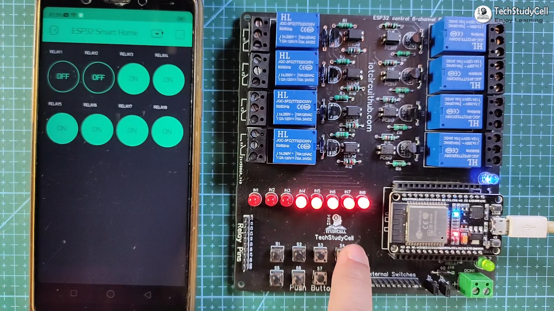
Then you can control the relay module from Blynk App and push-button.
Connect the Home Appliances
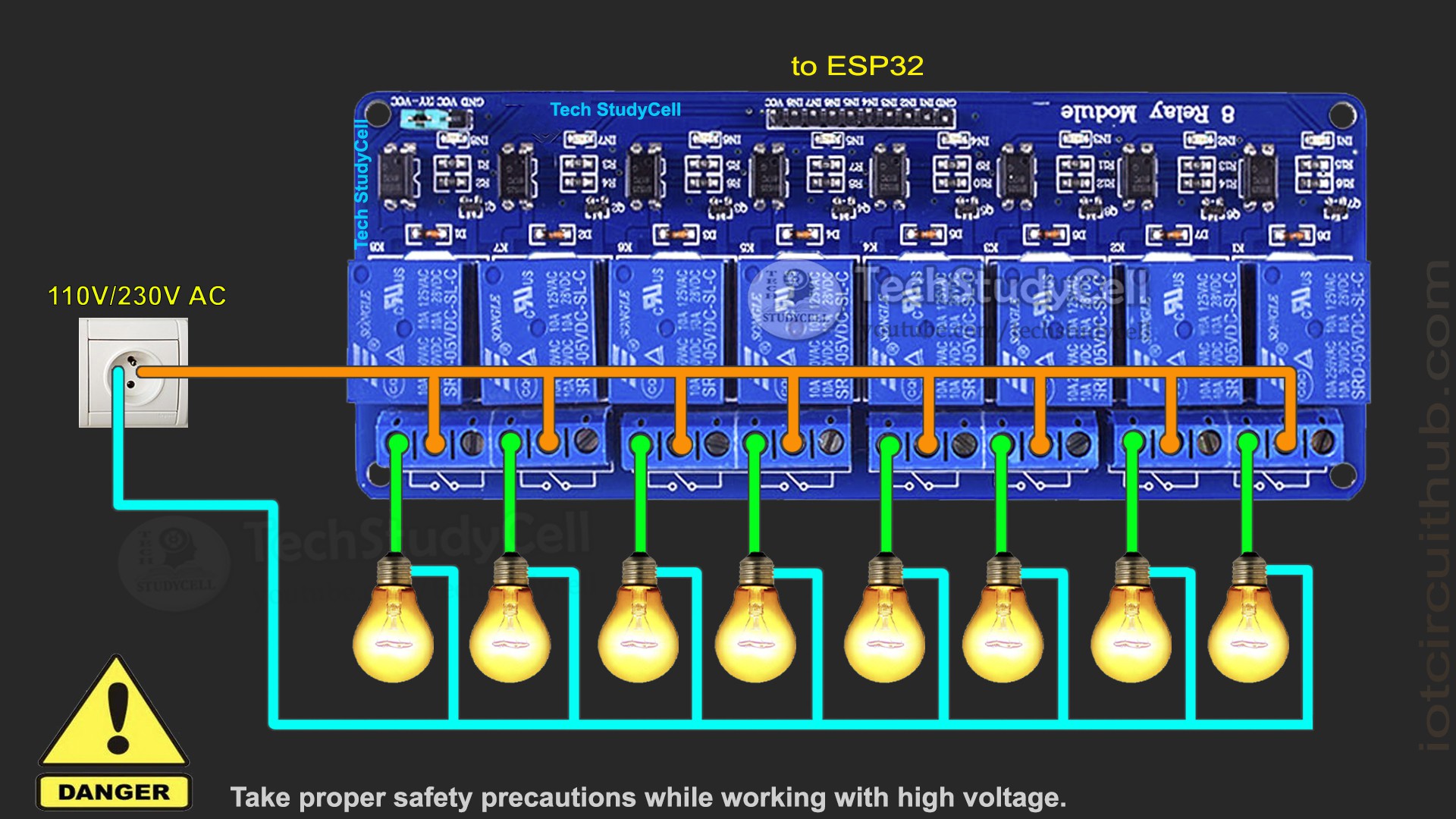
Connect the 8 home appliances as per the circuit diagram. Please take proper safety precautions...
Read more »