Vipin M
The project started off with a desire to use the Neopixel matrix panels and motors lying around in my stash. I started searching for ideas and came across a cool project, ULTiM8x8 modular, no-solder, RGB LED half cube, by jasoncoon. So, I decided to replicate it but with some changes to add motion.
The body was designed in Fusion 360 and includes a display with 3 Neopixel panels mounted on a turn table like platform. The display cycles through some animation sequences that can be changed over WiFi using a phone or any PC.
Below is the list of parts to be 3D printed and the required electronic components:
- a canopy which has 3 square faces to install the Neopixel panels at right angles to each other.
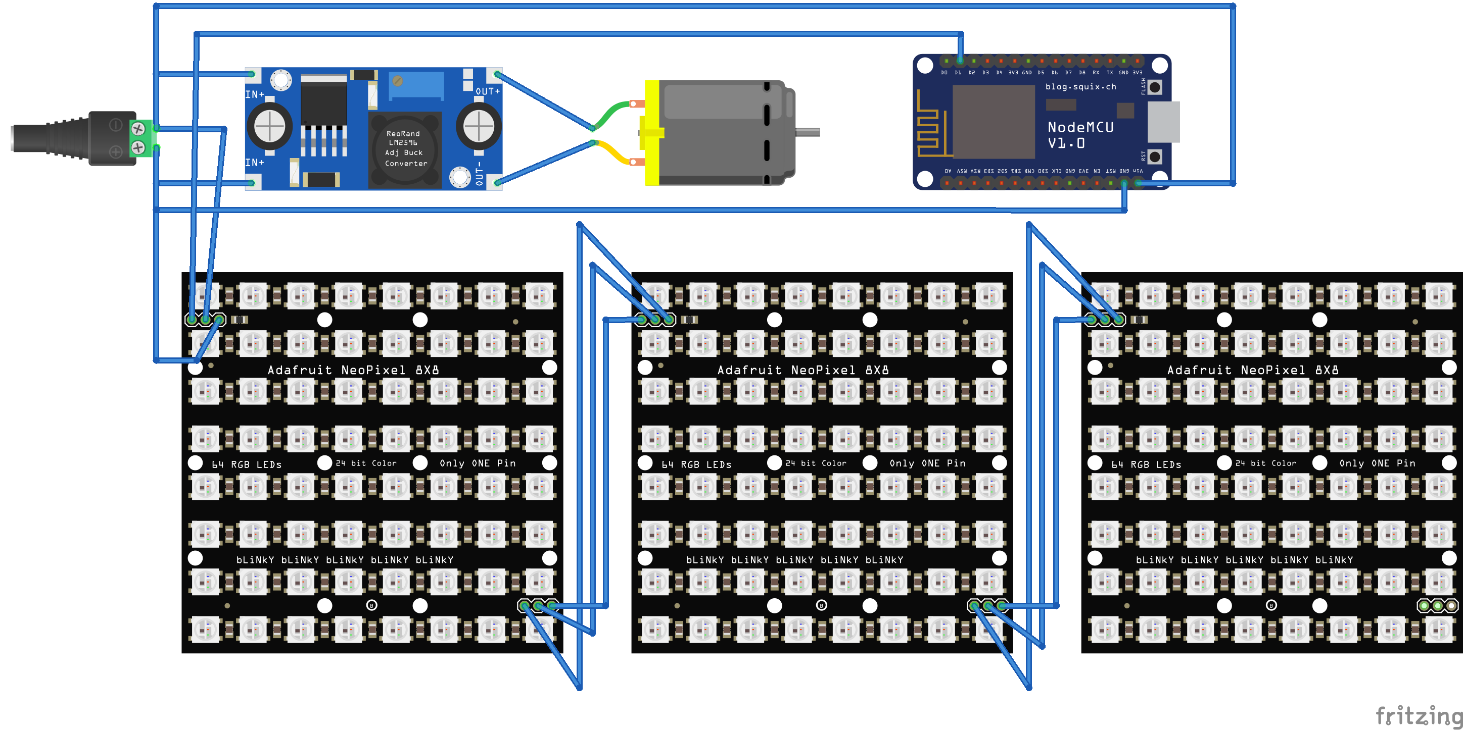
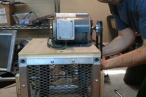
- a base which is a cylindrical housing to situate the electronics including the microcontroller, DC motor, slipring and the buck converter. The power input and the switch is also located here.
- a slew bearing with 90 tooth which is printed in place. The spacing between the inner and outer ring is 0.5 mm and could be a tight fit. So, make sure that the printer is tuned accordingly.
- a mounting bracket which keeps the DC motor and the slip ring in place. The rest of the electronics can be mounted on or around the bracket.
- a 15 tooth spur gear which is mounted on the motor shaft and mates with the slew bearing with the gear ratio 6:1 to reduce the speed and increase the torque.
- the Neopixel LED panels and the corresponding lids. The lid serves to unify the final look and diffuses the light from the otherwise very bright LEDs.
- For the microcontroller, I decided to stick with ESP8266. It has WiFi which can be used to remotely change the display patterns or update the firmware over the air. It is inexpensive and generally packs in a lot of punch in a small package.
- A slipring to join the upper and lower sections. More about this further in the builds logs.
- A switch and a barrel jack for power input from a DC adapter.
All parts were printed in PLA with 0.28 mm layer height and a 4 mm nozzle on an Ender 3. The STL files can be found on Thingiverse.
Click on the github link for changes to the code on top of the original repo.
Design choices
One unique challenge I faced in the beginning of the project was to transfer the power and signal from the base to the moving canopy. I searched up and found a few solutions including the use of hollow core motors or simply use an independent power source. The former was a bit expensive for my taste and the latter was a little inconvenient. So, I decided to go with an easy and relatively inexpensive option i.e. a slipring.
A slip ring is an electromechanical device that allows the transmission of power and electrical signals from a stationary to a rotating structure. However, after digging a bit deeper, I noted that there was some concern around the electrical noise that is introduced with the use of a slipring. It was a bit of a leap of faith since the control signal for the Neopixels has a rather strict timing requirement but it turned out ok. May be the quality of sliprings has improved and the noise effects may not be pronounced for small voltages and current.
Another tricky part was to figure out the mechanism for moving the canopy. All I knew was that I have to use gears but wasn't sure of the actual design. After some bit of thinking and tinkering, I designed a simple mechanism to have a gear in the center colinear with the slipring and transfer the power to this shaft from another gear and the motor installed next to it. However, then I came across a clever bearing design in the project Arduino controlled photogrammetry 3D-scanner, by Bribro12. So, I redesigned the part for my requirements and decided to use that instead.
A bit about the power requirements. The LEDs, microcontroller and the DC motor supply are all in parallel. The main supply comes from a 5V DC adapter capable of sourcing at least 3A of current. A single neopixel draws around 60mA of...
Read more »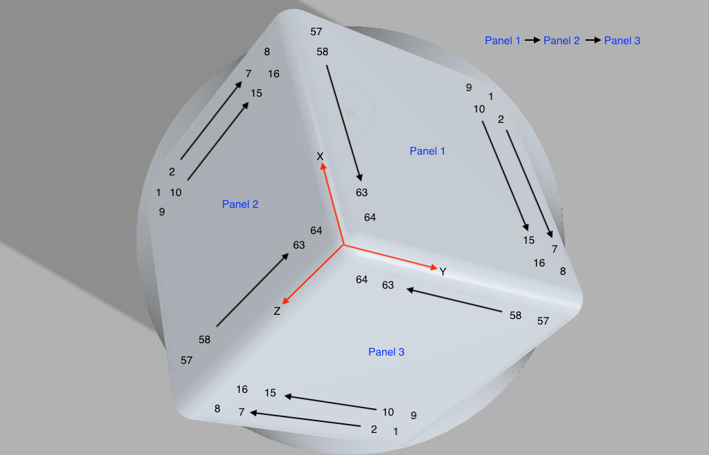
 Scott Swaaley
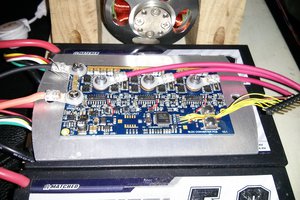
 Jarrod