As far as projects go, this one was actually really straightforward. If it weren't for the tedious calibration steps, this could have easily been a one- or two-day project. Here's the breakdown:
Hardware
The hardware for this project is super simple and super cheap. Each window consists of the follow components:
- Stepper Motor and Driver Board
- 1/2 in PVC pipe cut to length
- Curtain (mine were cut from discarded black-out curtains)
- 3D-printed motor mount
- 3D-printed idler mount
In addition to this, there was also a main controller board that drives both windows. It is made up of an ESP8266 Huzzah Breakout and a 5V 4A power supply, both from Adafruit. All together, this project should cost less than $50, depending on what you have lying around. I had almost every single part spare, so all I needed was the power supply and ESP8266.
The Control Board
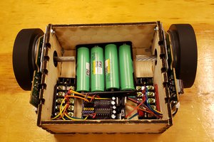
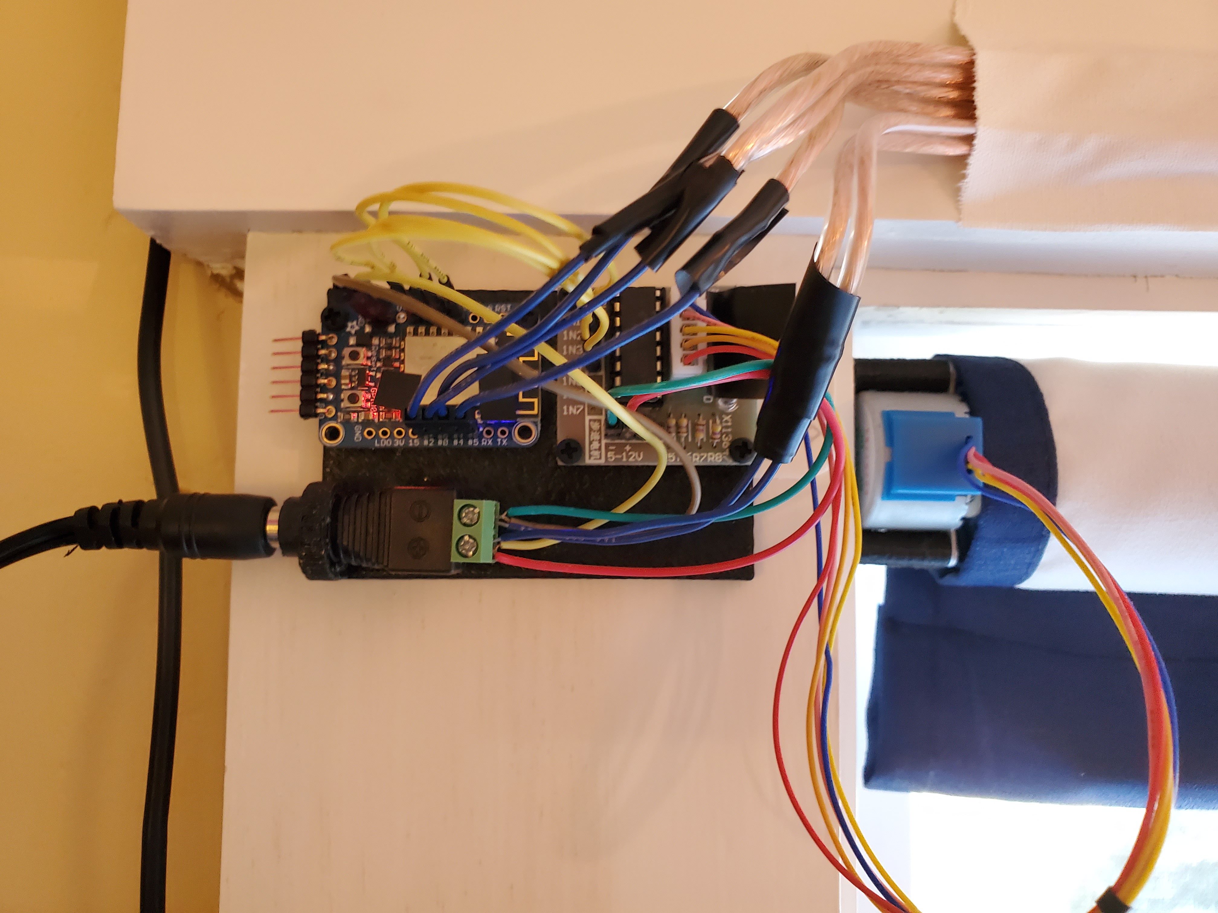 This is the setup that actually drives the stepper motors. The top part of the board has the ESP8266 jumpered over to a stepper driver board. The bottom part of the board breaks up the incoming power the ESP and the motors. The construction here is as simple as soldering in headers and connecting the right pins together. I decided against soldering the wires straight to the board in the even that I wanted to make some modifications later on (I was also being a bit lazy). The only weird thing is the wires coming out the top: those go to the other window. I didn't have much in the way of wiring laying around, so I used some spare speaker wire to bridge the gap. That side looks like this. It's the same wiring, just with extensions. I call this side the Aux board.
The Mounting Hardware
All of the components needed to mount the blinds and electronics to the wall are 3D-printed and available to download here. There are three groups of component: Wall components, Tube components, and Board components.
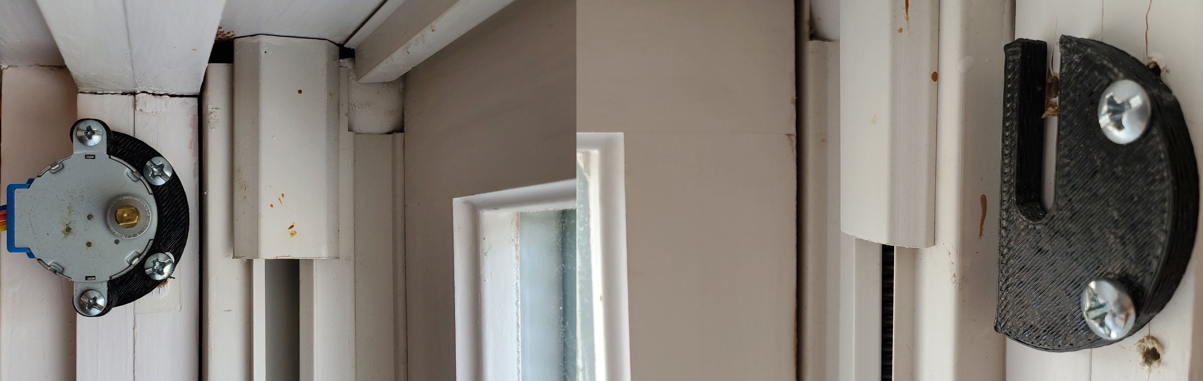
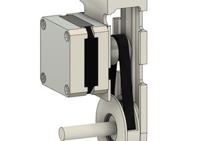
The Wall components help fix the stepper and idler ends of the blinds to the walls/window frame. Both sides use two screws to attach to the window frame. The stepper side (left) has mount points for the stepper motor and the idler side (right) has a channel that lets you slot in the tube. In newer versions of the idler side, the channel is sloped to make it easier to insert the tube when the blinds are mounted close to the top of the window frame.
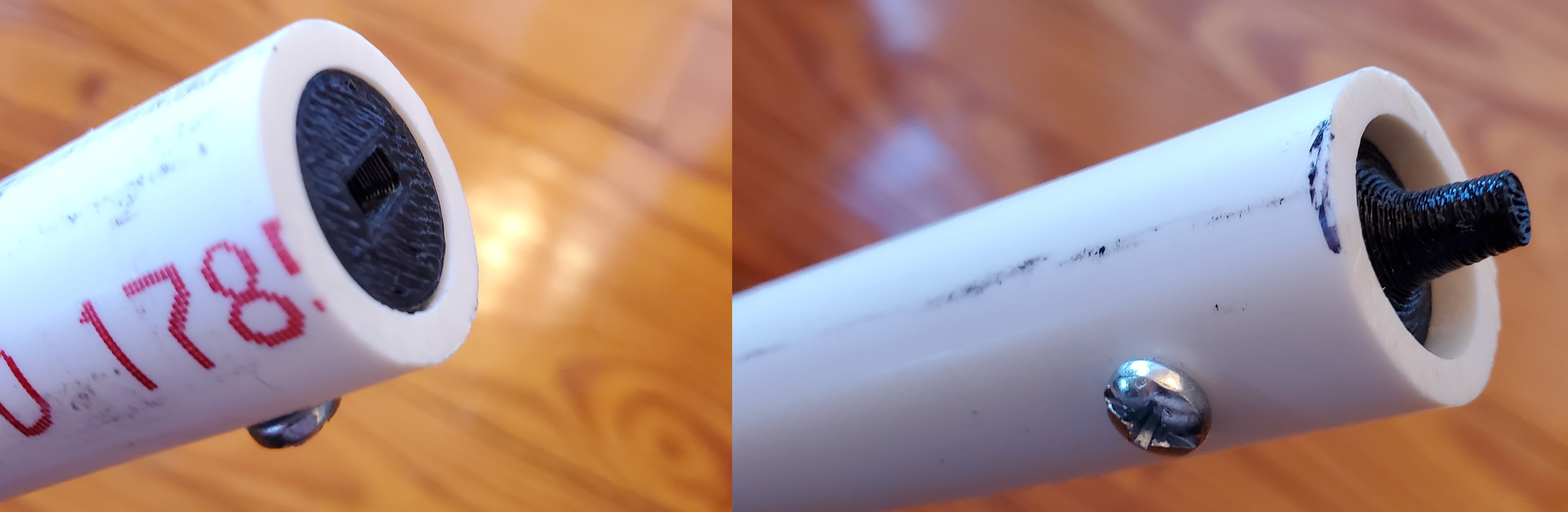
The Tube components connect the PVC tube to the stepper motor and provide an axle for the blinds to idle on. The stepper motor side (left) is just a cylindrical insert with a rectangular hole for the stepper motor head. The idler side (right) is another cylindrical insert, but with a taper to it. This tapered cylinder sticks out and slots into the idler channel. If you find that the tube is too long, you can easily slide the idler insert further into the tube until it fits into the window frame.
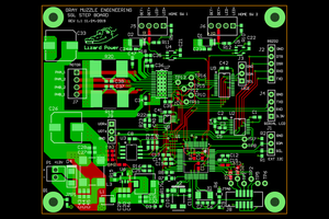
Finally, the Board components are handy mounting plates that the electronics can screw into. These plates can just be stickied to the wall with Command strips, gaffer's tape, etc. You can see these plates in the background of the photos in the Control Board section. The Control side has holes for the ESP8266 and a stepper motor driver. It also has a little arch for the power supply adapter. The Aux side (left) only has mounting holes for the stepper driver, since it's controlled by the ESP8266 mounted to the other window. You can just barely make this board out in the auxiliary board photo, but it's hidden pretty well by the stepper driver.
The Curtains
This is the main event, luckily it's not too hard. My curtains were cut from material I had lying around from some old black-out curtains. To cut these, I measured out the length and width of my windows and marked that up on the fabric. I left a lot of extra length since I wanted some curtain to still be on the rod even when the blinds were fully rolled down. I also left some space in the bottom for a metal rod to help keep tension on the blinds when they were being rolled up. I found...
 shane.snipe
 Bharbour
Great job on the motorized blinds project, Alex! The detailed breakdown of the hardware, control board, mounting components, and the software using ESPHome is impressive. The calibration effort paid off for smooth operation. By the way, have you considered implementing this for duo roller blinds?nzblinds.co.nz/product/blackout-duo-roller/