even with this cover, noise can still range +/-2 to 3mm, but it can be eliminated with DPS filter processes.
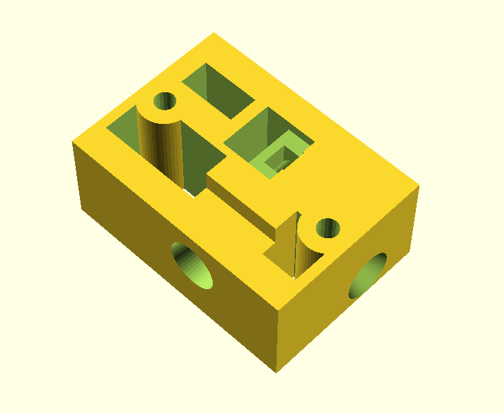
in order to build sensor housing, you will first need to print the main part. the file is included below this article.. use support settings to capture bottom of part details.
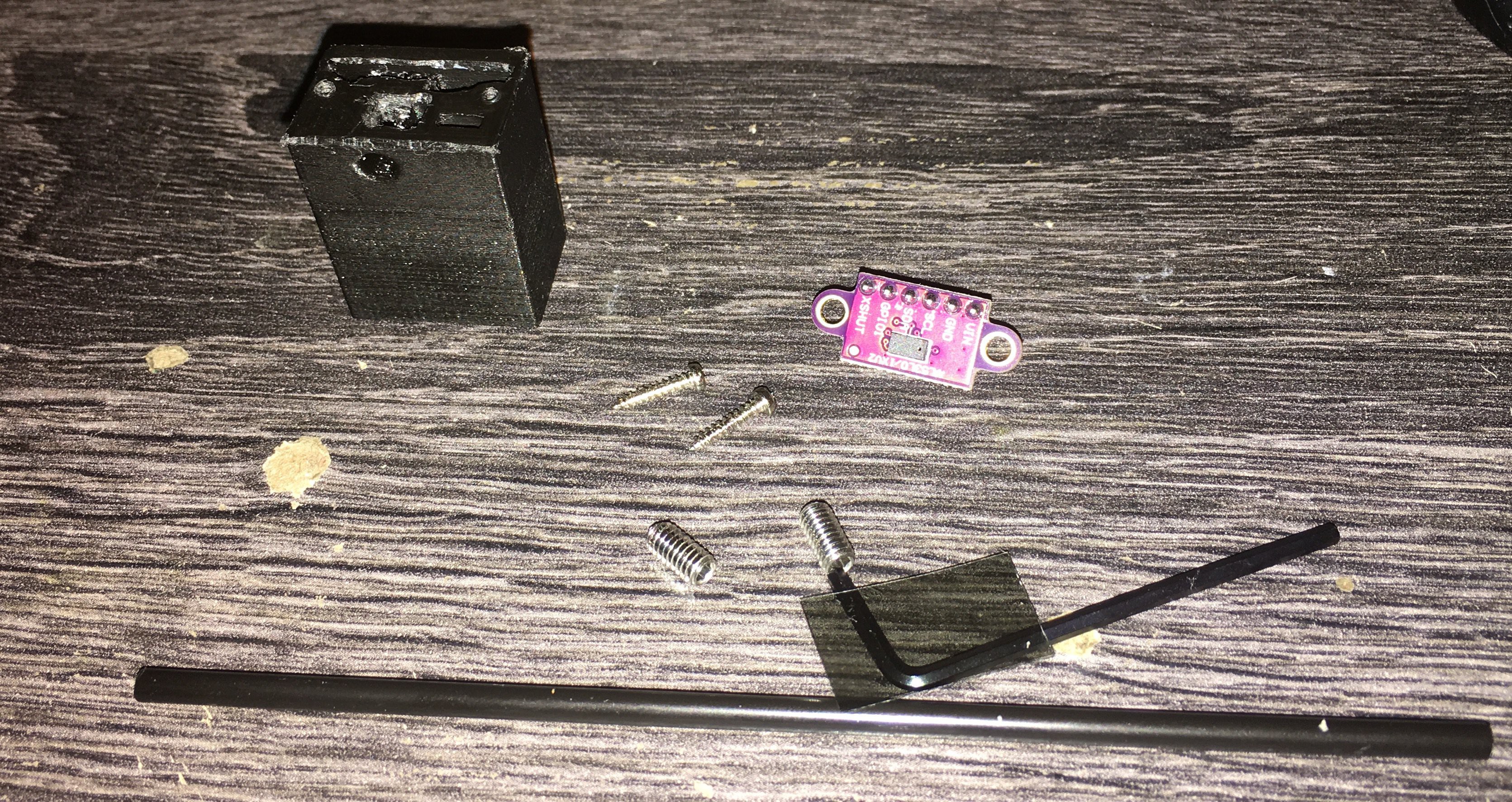
here are the needed parts:
2 4mm x6 or 8 length grub screws
2 2mm diam small machined screws. threading doesn't matter as it will self tap
polarizing filter ~15 mm x 22m
1 coffee straw to help stress fit the polarizing filter without scratching it.
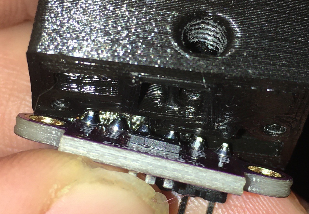
if the 3d part is correct in dimensions the VL53L0 sensor should sandwich between the board it is on and the plastic part. but dont mount it until after polarized filter step.
size and peal the polarizing filter.
add in the grub screws as in diagram. it does not matter what order they go in. but when adjusting light narrow the long side of the rectangle part first, or experiment.
with grubs in place, now take one side of polarized filter and slide it into the side corner of the rectangle. in the images you can see a slit inside the part that fits the filter. push the straw in from the back to help bend the filter, and curve it over to the other side for it to snap spring fit into place. it should be curved when seated.
make sure screen is clean and no particles are inside of lens area or where sensor will go.
align and put sensor in place. use small metal screws to position in place. dont tighten up until you can center the sensor in place. it has room to slide around.
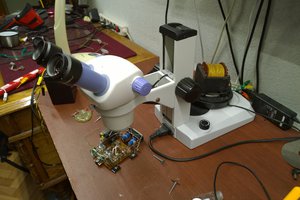
you will need an ir camera or a camera without ir filter to see the laser light and adjust size, or you could do trial and error.
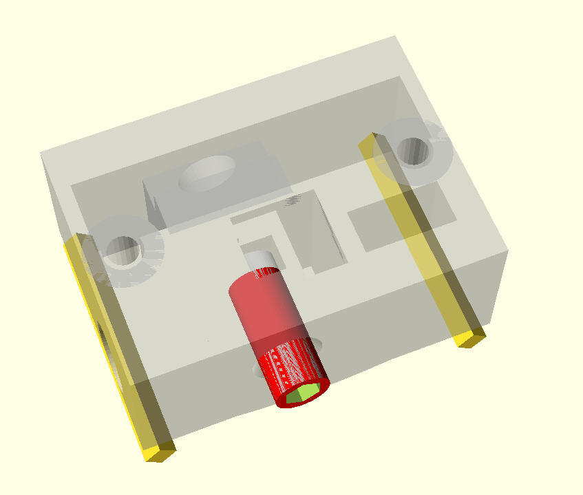
the images of the sensor purple light are false color images from IR filter being removed from camera. this is the area the sensor sends out a pulse and expects a return. only the closest object is measured, so anything within the lit area that sticks out will be at the valued calculated for. by default it is at 200mm distance about 55mm radius. from the designed part it has been reduced to a rectangle about 8mm x4mm.
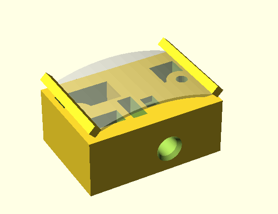
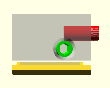
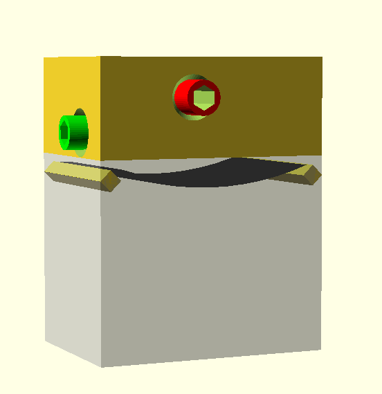
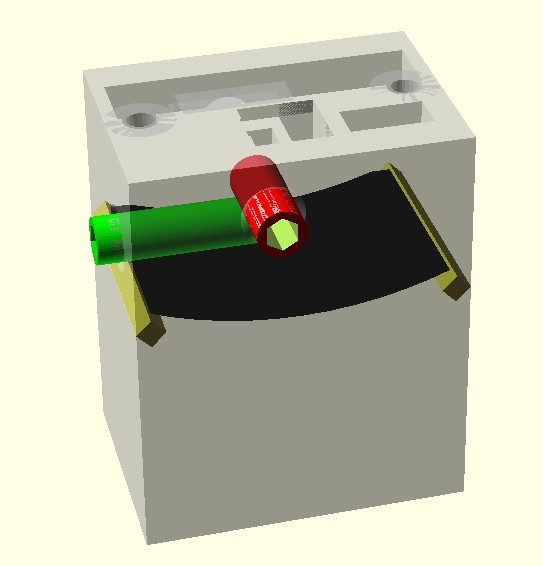
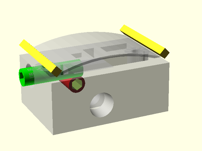
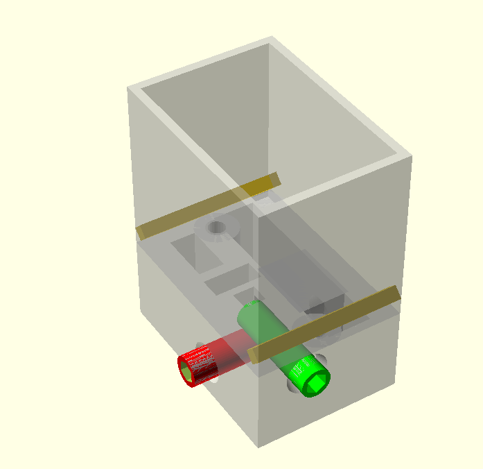
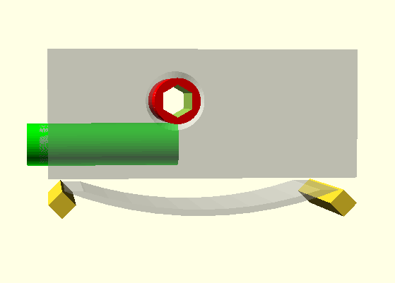
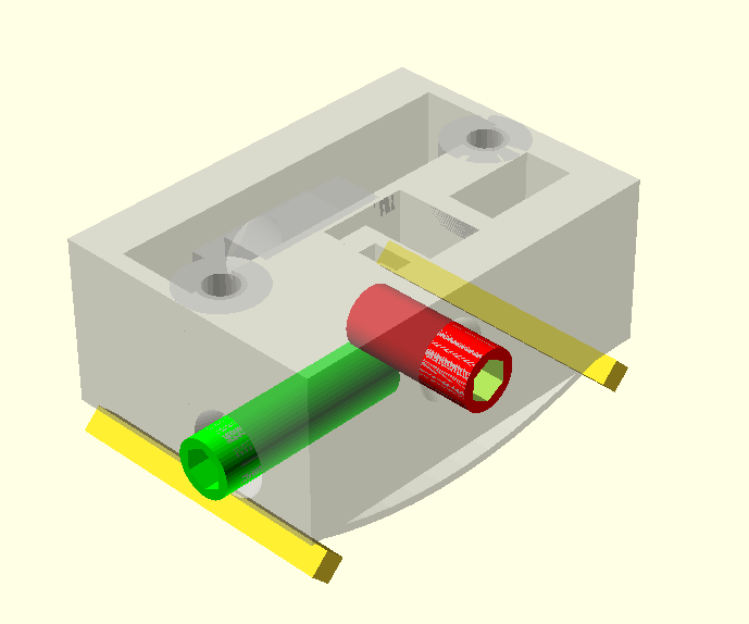
here are the images of the design casing which should give an example of how it works. it is adjusted by 4mm by 6 or 8mm deep grub screw placement and fine tuned with hex key wrenches.
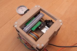
the first image is of the part with the outer box shield removed to show the polarizing filter.
the red and green colors show the grubs screws.
 DeepSOIC
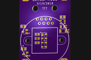
 Ted Yapo
 Osman Mazinov