 Vedant Paranjape
After all the tools arrived required for soldering, it was time for some action. I started with applying solder paste on the board, since I didn't have a stencil, I used sewing needle to apply paste on to the pads, it was a cumbersome process and I had to wipe the board twice, but once I got the hang of it, all went good
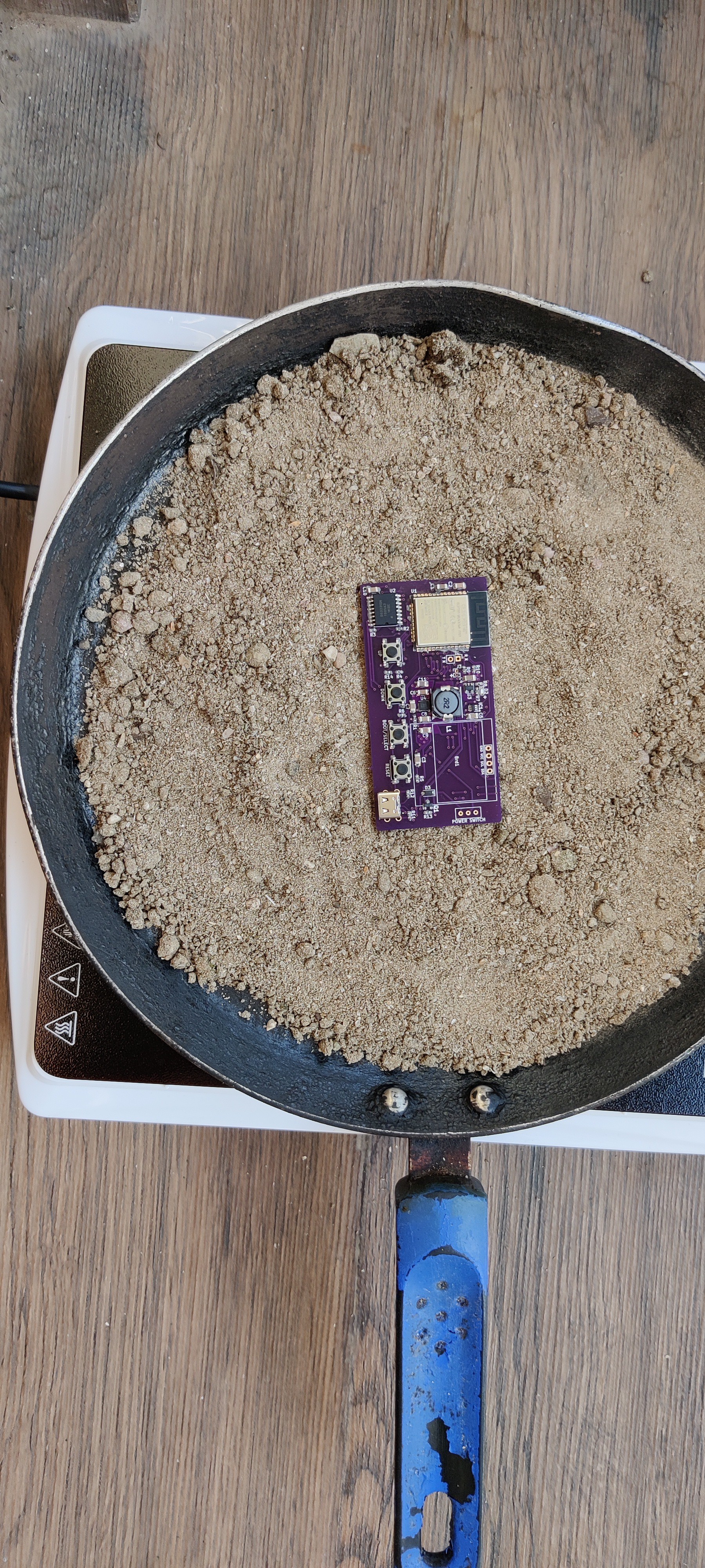
I was a bit worried about TPS63001 regulator, as it was the smallest with WSON package. Next I placed components on it one by one, and then turned on the makeshift reflow oven. Preheated it till it reached 100 C and then placed the board on sand, and let it cook for some time.
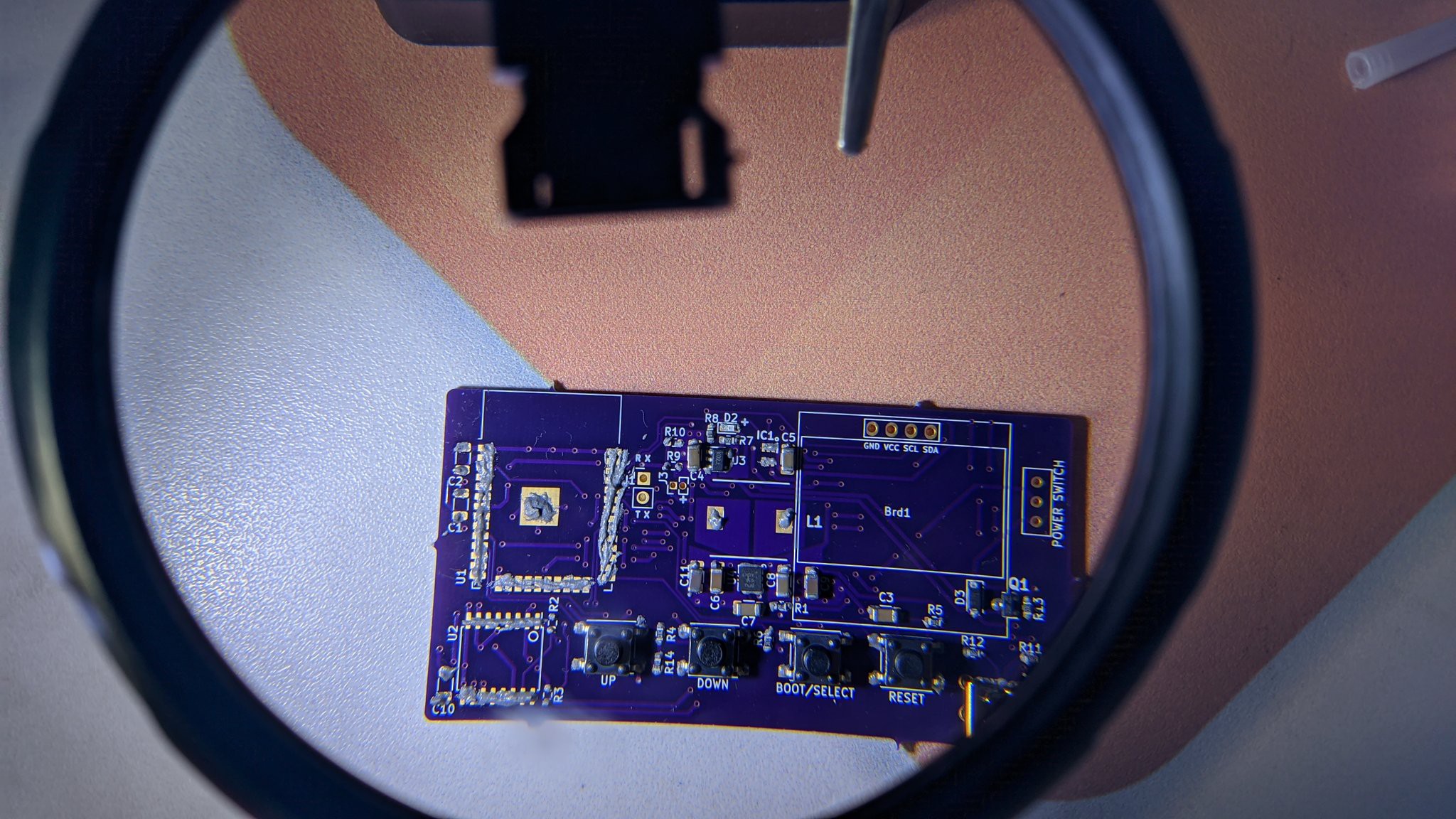
As soon as the temperature reached 185, the solder started turning silvery, I let it be as such for a few minutes to make sure all joints were soldered appropriately. Then turned it off and let it cool for half a hour. Here's the final board, there were several bridges here and there, I removed all the visible ones using flux and solder wick.
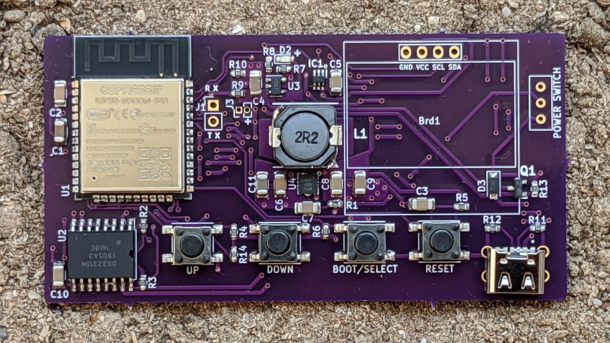
Solder bridges are visible if you look closely, check on the RTC chip, USB terminal and the WSON regulator (there's a small bead). These were easily fixed, but there was a demon sitting on the ESP32 and worst part is that it was not visible to the bare eye and hence I missed it. What followed was 2 days of hell debugging, as to why the ESP32 wasn't getting flashed. It went into boot mode, but as soon as bootloader was flashed it failed to write to the flash chip, reason being a solder bridge shorting pins in the bottom row. I had to clean it up and boom, it worked like that.
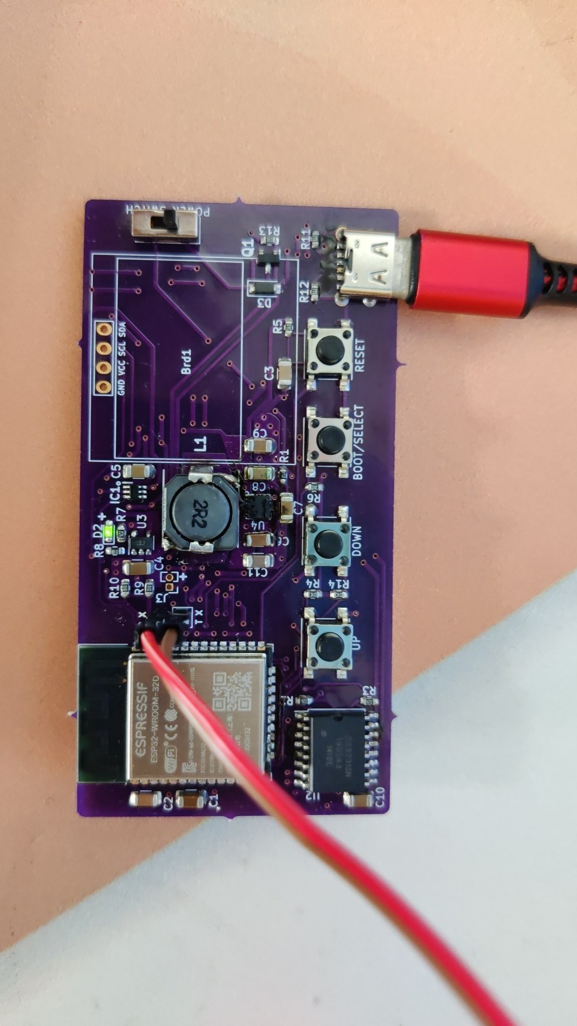
Now, that ESP32 was working, I checked the other peripherals, buttons, battery charger and OLED worked fine. But the RTC just won't work, apparently reason being solder bridges on ESP32 side. But little did I know this, eventually found a short, SDA and SCL pins were shorted. So I removed the chip and replaced it, also removed the pull-up resistors, still it won't work, finally it clicked, the ESP32 side was shorted. The solder joints were invisible to eye, nevertheless, fixed it and it worked great. So, it took 3 days just to get working, only if I had used a stencil it would have been much better.
Quickly developed a basic app, to test working of the RTC and OLED. It displayed the time and battery voltage that was read from the voltage divider.
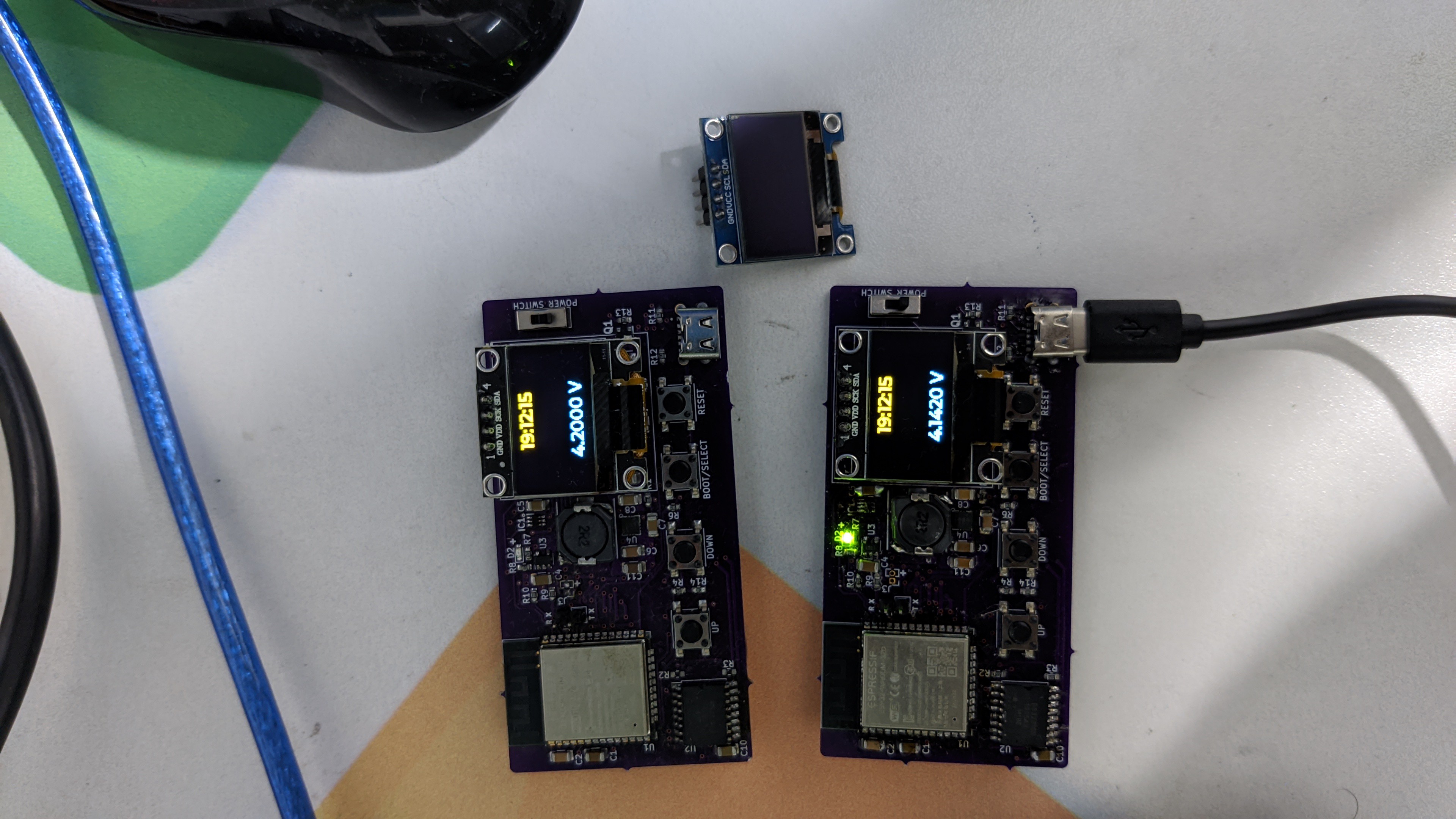
Yeah !! I assembled a 2nd board and this time, I got it running it just 2 hr.
Follow my project for more updates :)
Discussions
Become a Hackaday.io Member
Create an account to leave a comment. Already have an account? Log In.