This project was developed in partnership with Robô Lúdico School and JLCPCB Factory and offers 5 free PCBs of Arduino Compatible Board.
Have you noticed that most programming and Arduino classes are boring? Getting started is difficult, as there are no activities that are interesting and help us learn in a simple and easy way. How can we solve this situation for you to develop your first projects?
The first thing we must do is to teach with ease and simplicity what is difficult for many people.
Start by developing a project that is easy for you to learn the basic concepts of Arduino by manually assembling a practical and fun project. Arduino allows us to work with creativity and that's why we decided to help you with this project.
In this article, we will develop a project to control a Saint Claus and a Tree with a board compatible with Arduino UNO. In the end, you will receive a beautiful gift! Wait for the end of this text!
We are going to develop the following project, which is presented below.

As you can see, we can control all the LEDs on the tree and Saint Claus Arduino Module.
Therefore, in this article you will learn:
- How to assemble your first Arduino Module with Arduino;
- How to create your first module project with Arduino;
- How to create your first programming to control LED modules.
- Develop a robotics workshop with fun kits.
Next, we will start the full discussion of the Christmas project with the Arduino and the Santa Claus and Christmas Tree Arduino Moduleboards.
Developing the fun Christmas project with Arduino
The project consists of creating a system to control Santa Claus and the Christmas tree Arduino Module through animations and effects with the LEDs of the modules.
Based on this idea, the following circuit was developed to control them.

In the circuit above we have an Arduino controlling Santa Claus and the Christmas tree Arduino Modules.
So, as you can see, Santa has 4 LEDs and a button. The Christmas tree Arduino Module has 7 LEDs. All two modules have connection pins to connect the cables with the Arduino.
Next, see the 3D structure of each module presented in the circuit above. First, let's show you the structure of the Santa Claus Arduino Module.
The structure of the Santa Claus Module for Arduino
Below is the 3D structure of the Santa Claus Arduino Module. As already mentioned, it has 4 LEDs and 1 button. This button can be used for any purpose.
You can, for example, place the button connected to the Arduino, press it, and modify the animation style of the LEDs. Use your creativity and do what you want!
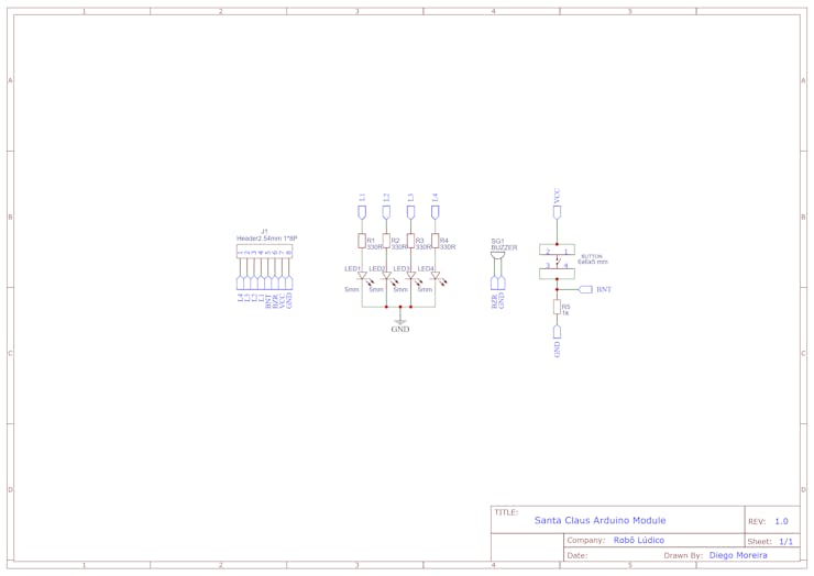
In addition to the buttons and LEDs, the card has a buzzer. It is great for making sound signals with the Arduino. Have you ever imagined making a Christmas melody with your schedule? Yes, it is possible.
Now that you know how the circuit structure works, take a look at Santa's 3D board. You can view all connected LEDs, resistors, and buttons. The buzzer is connected to the back of the Santa Claus Arduino Module.

Resistors are very important and are used to limit the current of the LEDs and to assemble the Santa Claus Arduino Module button circuit.
Now, let's look at the Arduino ModuleChristmas tree circuit.
The structure of the Christmas Tree Arduino Module
The structure of the Arduino Module Christmas tree is simple and consists of 7 LEDs and 7 current limiting resistors. You can use 330R values up to the 1kR value.

The electronic schematic is quite simple and from it we have the result of the Christmas tree. Below is the 3D Christmas tree with all LEDs and current limiting resistors connected.

After understanding the functioning of the module structure, we will see the programming logic developed to control them.
For this project, we'll use the JLCPCB Arduino Compatible printed circuit board presented below.

You can obtain the Arduino JLCPCB compatible PCB for your projects for $2 in your first order with the link: Earn my PCBs Arduino Compatible.
Use the JLC-RECE coupon, earn a $2 off discount, and earn 5 PCBs.
The programming logic for controlling the modules
Next, we have the complete logic to create an effect of turning the LEDs of the modules on and off.
byte pinos = 0;

void setup() {
  // put your setup code here, to run once:  for(pinos = 3; pinos <= 13; pinos++)  {    pinMode(pinos, OUTPUT);    }

}

void loop() {    // put your main code here, to run repeatedly:  for(pinos = 3; pinos <= 13; pinos++)  {    digitalWrite(pinos, HIGH);    delay(50);  }
  for(pinos = 3; pinos <= 13; pinos++)  {    digitalWrite(pinos, LOW);    delay(50);  }

}
In the code above we have the variable pins. It will be used to manipulate the Arduino pins.
byte pinos = 0;
After the declaration of the variable, we have the function void setup. Within this function, we made the configuration from pins 3 to digital pin 13. All of these pins will be used to connect Santa Claus and the Christmas tree. The function is shown below.
void setup() {
  // put your setup code here, to run once:  for(pinos = 3; pinos <= 13; pinos++)  {    pinMode(pinos, OUTPUT);    }

}
Note that we use the for loop to configure all pins 3 through 13 as digital outputs. The loop allows us to avoid running the pinMode command multiple times.
Thus, with a single command, we make several iterations from 3 to 13 to configure all these pins as digital outputs.
After that, we have the loop function. In the loop function, we carry out all the control logic for each LED of Santa Claus and the Christmas tree.
The loop structure is shown below.
void loop() {    // put your main code here, to run repeatedly:  for(pinos = 3; pinos <= 13; pinos++)  {    digitalWrite(pinos, HIGH);    delay(50);  }
  for(pinos = 3; pinos <= 13; pinos++)  {    digitalWrite(pinos, LOW);    delay(50);  }

}
In the first for loop, we activate each LED. We start the drive from LED 3 to LED 13. After each LED is activated, the Arduino waits 50 ms.
for(pinos = 3; pinos <= 13; pinos++) { digitalWrite(pinos, HIGH); delay(50); }
When all the LEDs are activated, the code flow enters the second for. The second for loop is shown below.
for(pinos = 3; pinos <= 13; pinos++) { digitalWrite(pinos, LOW); delay(50); }
The for loop is executed and all LEDs will be extinguished individually. Start to turn off from 3 to LED 13. With each LED off, the Arduino waits 50 ms.
Now I want to give you a gift and a very interesting strategy for you to do with these modules.
Strategy and Christmas Gift
This strategy is for you who is a teacher or a student and want to put your knowledge into practice. You can manufacture these electronic boards and set up a teaching workshop with your friends or students.
That way, you can set up the following teaching structure:
- Explain what an electrical circuit is and how a printed circuit board works;
- Explain the welding process and protective equipment for welding electronic boards;
- Welding the electronic boards;
- Show the basic and introductory concepts of programming;
- Write the code on the Arduino and show the board being controlled;
- End the class with the review and delivery of new exercises.
Now, so that you can execute this strategy I want to give you a Christmas present. Click on this link and receive your gift!!!
Acknowledgments
We thank the company JLCPCB - Printed Circuit Board Factory for the support and partnership in the development of this project with Robô Lúdico School.