0%
0%
PaperClip Computer
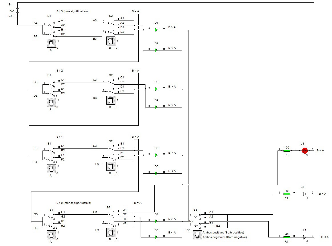
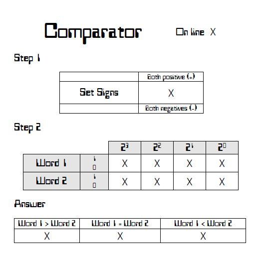
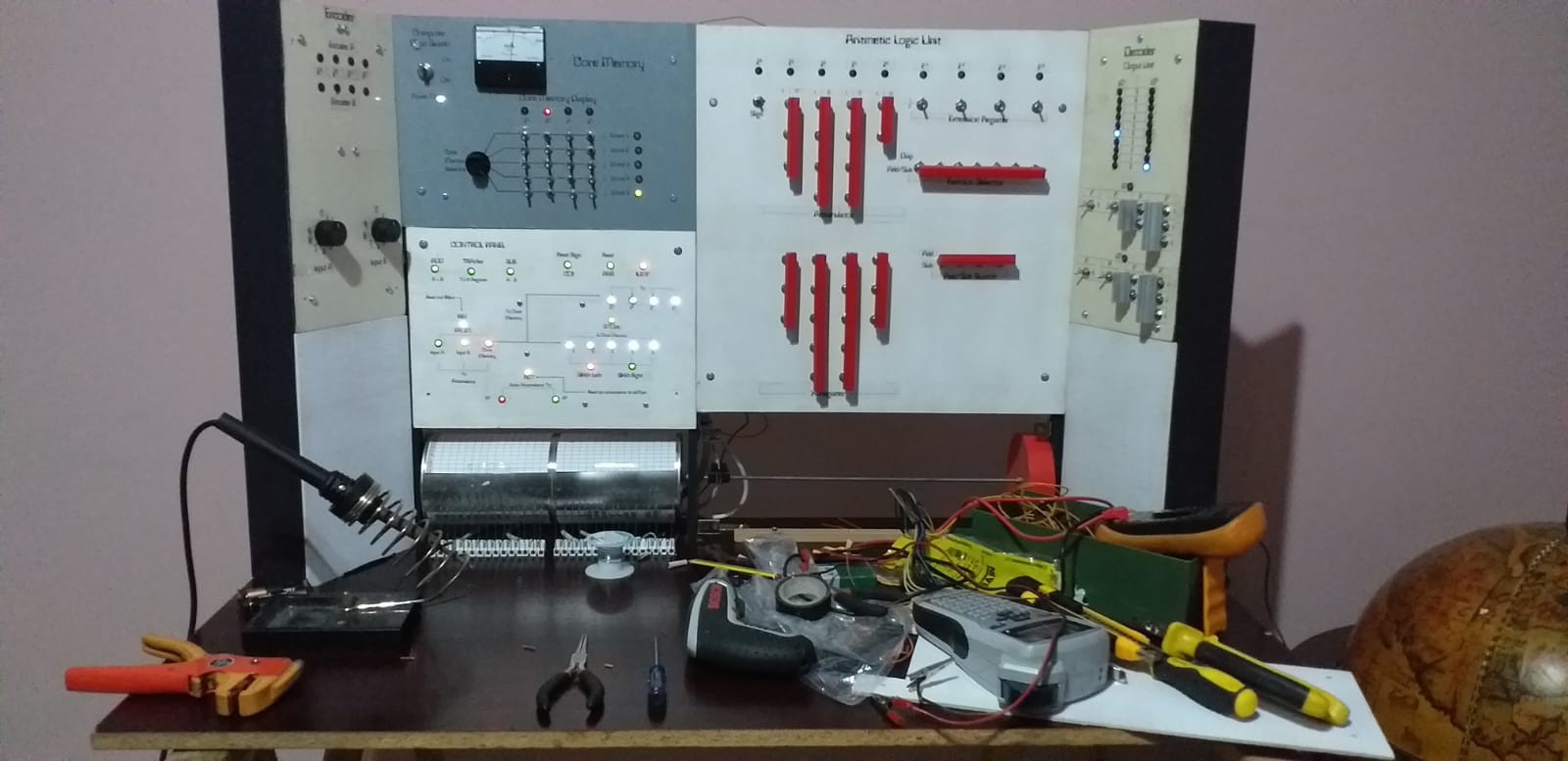
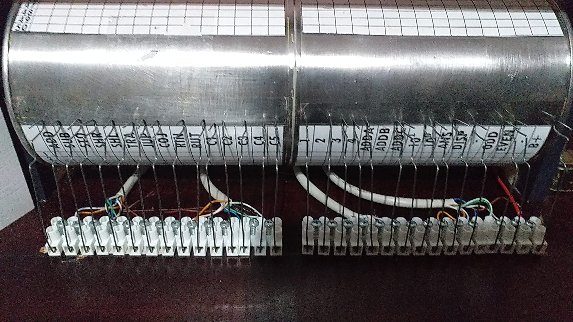
A few months ago I discovered "How to Build a Digital Computer That Works" and got excited about the project.
 Marcelo
Become a Hackaday.io member
Already have an account? Log in.
Just one more thing
To make the experience fit your profile, pick a username and tell us what interests you.
Pick an awesome username
hackaday.io/
Your profile's URL: hackaday.io/username. Max 25 alphanumeric characters.
Pick a few interests
Projects that share your interests
People that share your interests


 Stefano
 Michael Gardi
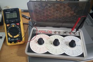
 deftcoyote
Simply wonderful! I'd forgotten about this book on my bookshelf. This along, with early Xerox copies (the ones that felt waxy and smelled funny) of the Cosmac Elf articles from Popular Electronics helped foster my early understanding of computers and digital logic.
I see that archive.org has a scanned copy of the book available.
https://archive.org/details/bitsavers_paperClipCorkingDigitalComputerJun67_11243437
Now that I'm waxing poetic - a link to the Elf as well:
https://en.wikipedia.org/wiki/COSMAC_ELF