 Marius Taciuc
Reason
As some of you probably saw in the description of my profile, I used to work years ago as a HW design Engineer for a multinational company and later I moved to Papua New Guinea. I've been working as a radio and maintenance Engineer there helping some aid organizations the development of the 3rd world countries. This month I returned from my exotic journey around the world and I thought of publishing the plans of this clock to celebrate this transition. I hope that the entire exercise of posting these schematics will help me overcome the reverse culture shock in a smoother way.
About the clock
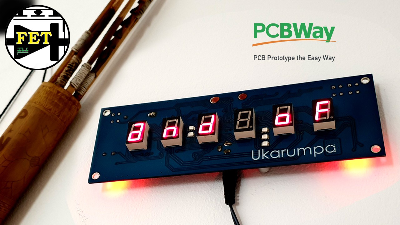
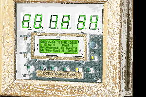
The clock uses normal 7 segments LED displays and it will have 6 of them. This will allow for the possibility of displaying 24h format times with minutes and seconds. In addition to the seconds displays, it will have an incrementing bar graph consisting of 5 leds which will increase with the count of the tenths of seconds. So every 10 seconds another LED on this bar graph will turn on. The LED bar graph will be split in two sections. Three LEDs will be positioned between minutes and seconds, and two of them will be the dots ":" between hours and minutes. This will create an interesting light effect.
Scrolling messages
As many of my clocks, this one will display 5 scrolling messages every sharp hour:
1) missing Papua New Guinea
2) the land of unexpected
3) home of 839 distinct languages
4) best snorkeling experience
5) hike through the jungle
Other features of the clock
- RTC time with coin battery memory retention
- Precise time and easy to set
- Possibility of year, date and temperature display
- Leap year automatic change
- PWM display dimming function that can adjust with ambient light
- Back light
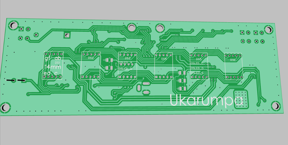
How it works
This clock uses the MSP430G2553 mcu as its brain. The software is written in C++ and I programmed it with the MSP430 launch pad and IAR Embedded Workbench. If you want to try to replicate this clock, I suggest you use the same programming environment for flashing the code into the device. Other platforms might use different compiling strategies and the resulting flashed size could differ from mine. The risks would be that the code might not fit into the flash memory or some of the timing sensitive delay loops inside the code might be affected by this.
 brett.oliver
 danjovic
 Maakbaas
 saarbastler