 Jake R.
Overview
For this step we are going to use diagrams to understand how our data is flowing through the module. We can gain some insight from the simulation and knowing the basics of filters can hurt either.
Top level block:
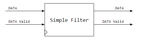
Nothing too fancy. Data comes in on an enabled line and data comes out the same way. Instead of drawing clock lines, we use the chevron symbol to show that this module is clocked. Our filter needs to run faster than our sampling rate clock so we can run the MAC through our coefficient list before the next sample comes in. The DATA Valid line lets the Simple Filter know that there is a new sample on the line. This enable line should be in sync with the Simple Filter processing clock and we are assuming that the module receiving the sample data is conditioning as such. Now for a closer look inside.
Internals
We are going to use some relatively simple logic elements to build our filter. The table explains each one:
 | Addressable Shift Register Samples come in and 10 samples later, they are removed. We can also address this module to get an data from any position in the register on the output. Clocked. |
 | Multiplier Multiplies two numbers. We will need to consider bit growth at some point.... Combinatorial |
 | Adder Adds two numbers. Combinatorial |
 | Register Holds a value of a signal wire. Clocked |
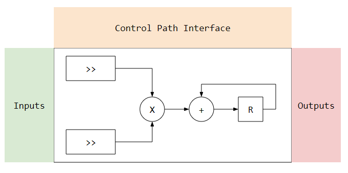
Using the elements, we can build a filter below. I have marked the areas I use to diagram up the connections between 3 main areas.
Inputs, are the inputs from the system into the data path section.
Outputs, are the outputs to the system from the data path section.
Control Path Interface, is all the controls needed to execute the operations on the data path.
Below shows the connections filled out.
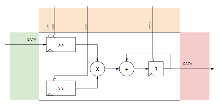
Notice that the control lines for DATA Valid are not present in this diagram. This signal will be used in the control path section and will help control the signals in the Control Path Interface.
Conclusions
With the data path processing outlined, we can start thinking about the control path and how we will control the 10 MAC operations in the data path.
Given that this is a simple design, there are a few glaring issues that will come up. The list includes things like, bit growth from the arithmetic, timing issues from the shift registers to the MAC, and flow control to let the system know we are busy so we don't miss a sample.
Discussions
Become a Hackaday.io Member
Create an account to leave a comment. Already have an account? Log In.