 Sina Roughani
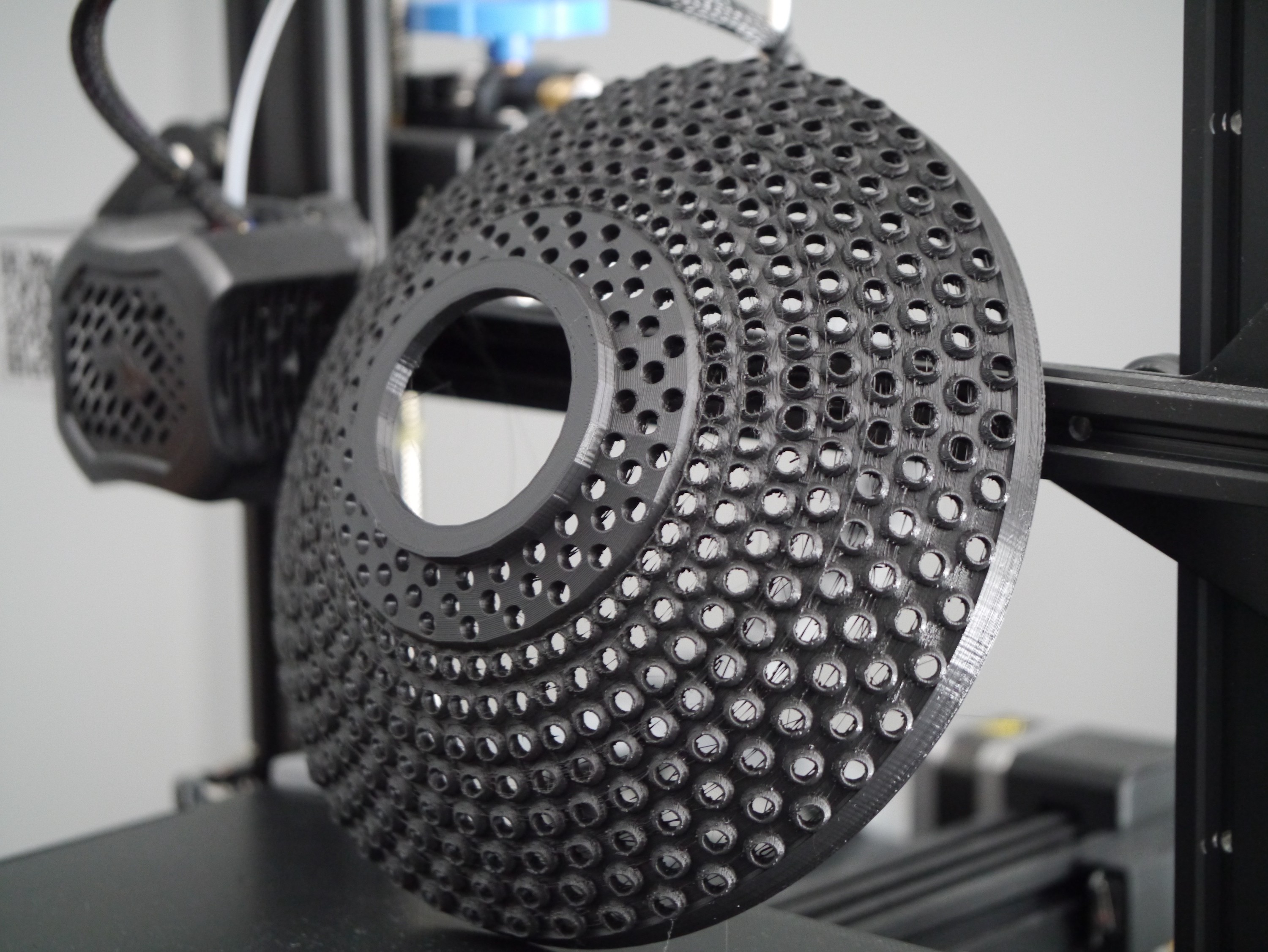
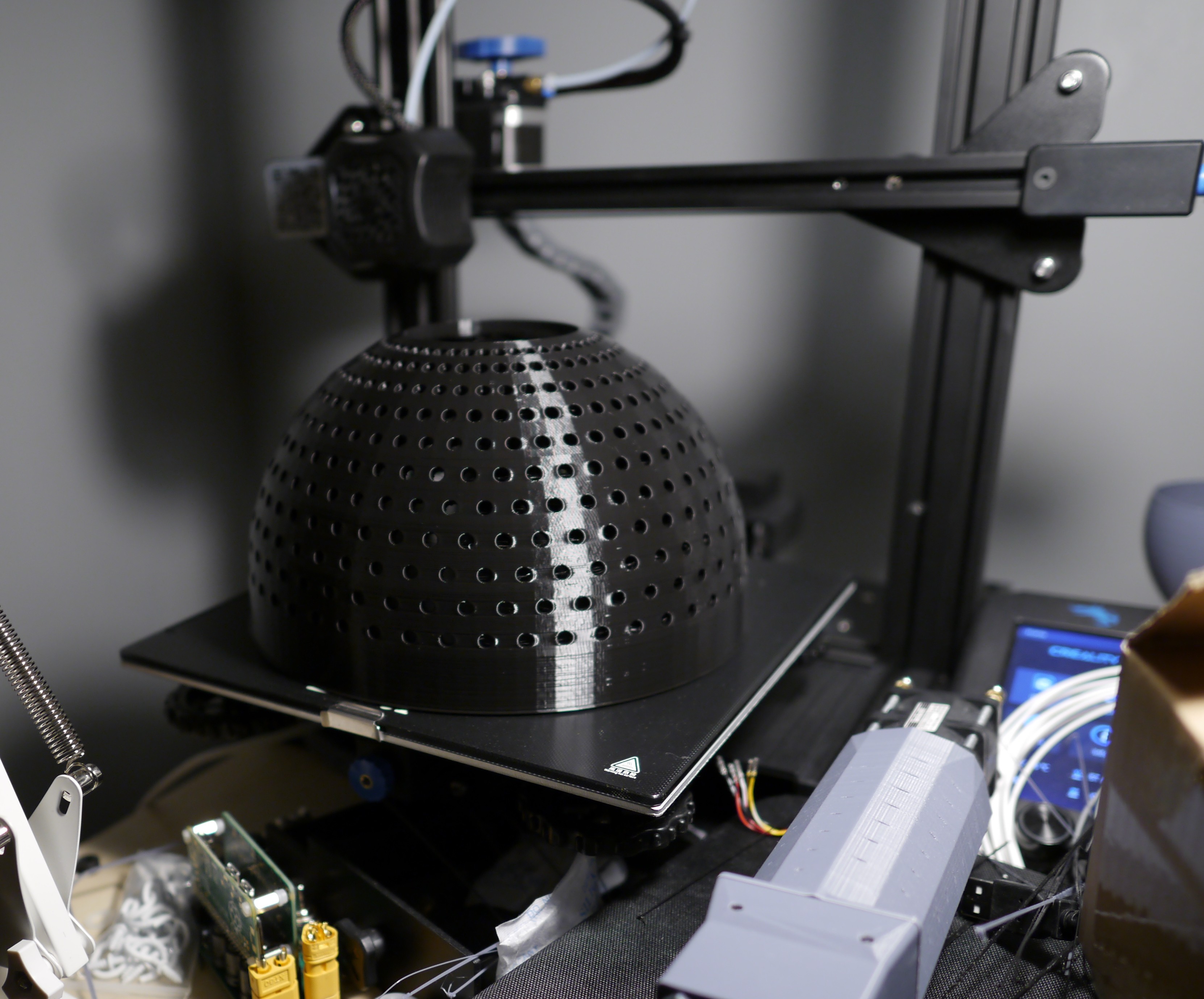
This project has 3 main phases. Printing the dome- needs a 220mm*220mm bed and a day resting on said bed. Inserting LED's- may be excruciating if you slice the print wrong. Soldering- using good solder and mastering the art of surface tension is critical.
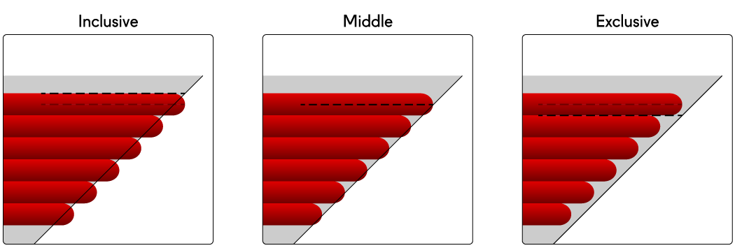
For slicing, be sure to use Cura's "exclusive slicing tolerance" feature. This will print the holes slightly oversized. You want the 5mm LED's to be able to fit without cracking the print or your fingernails. Use 125% flow on the infill and connect (gyroid) infill lines and alternate an extra wall to get the best part possible. That's my not-so-secret recipe for good prints every time.
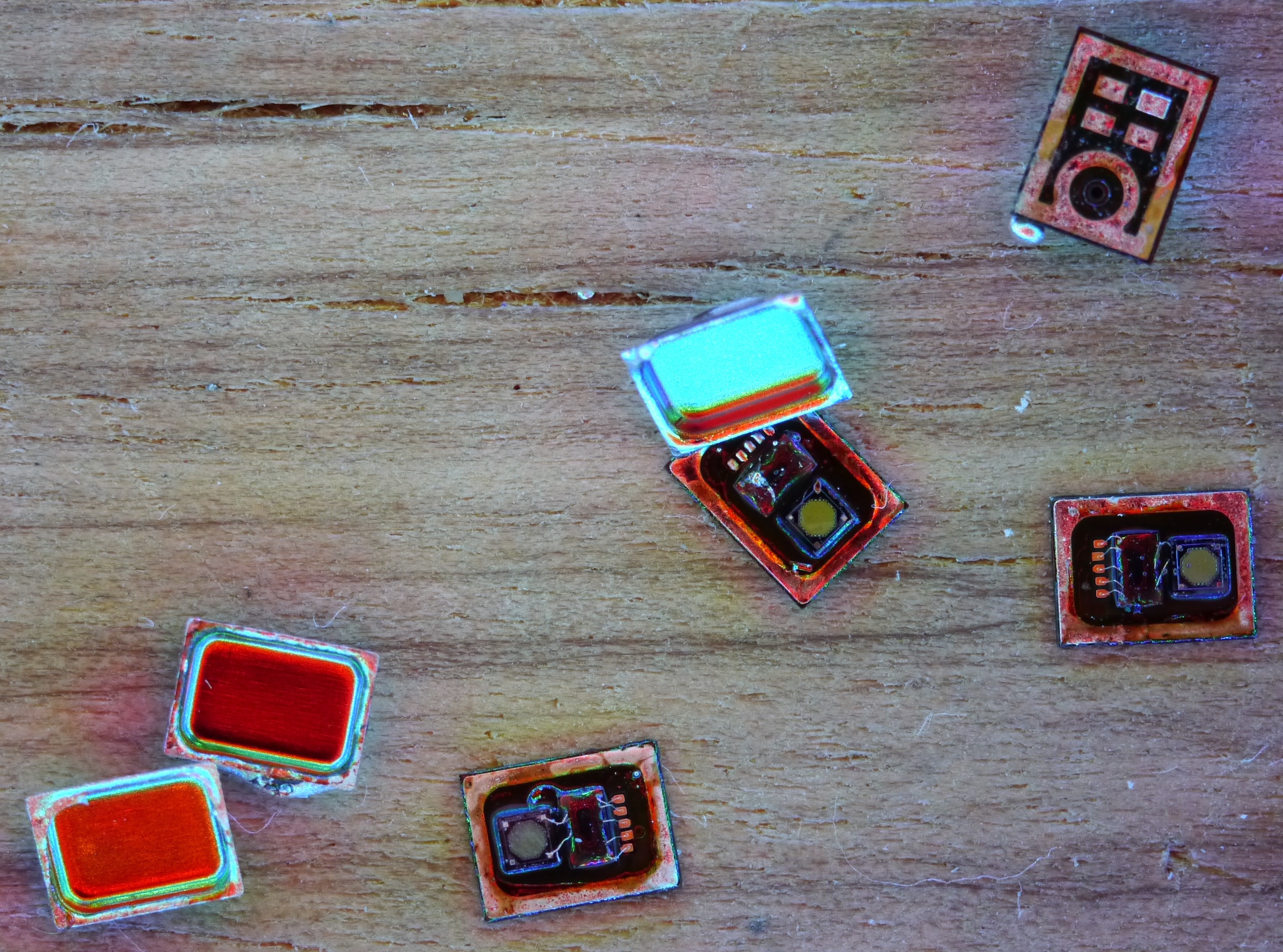
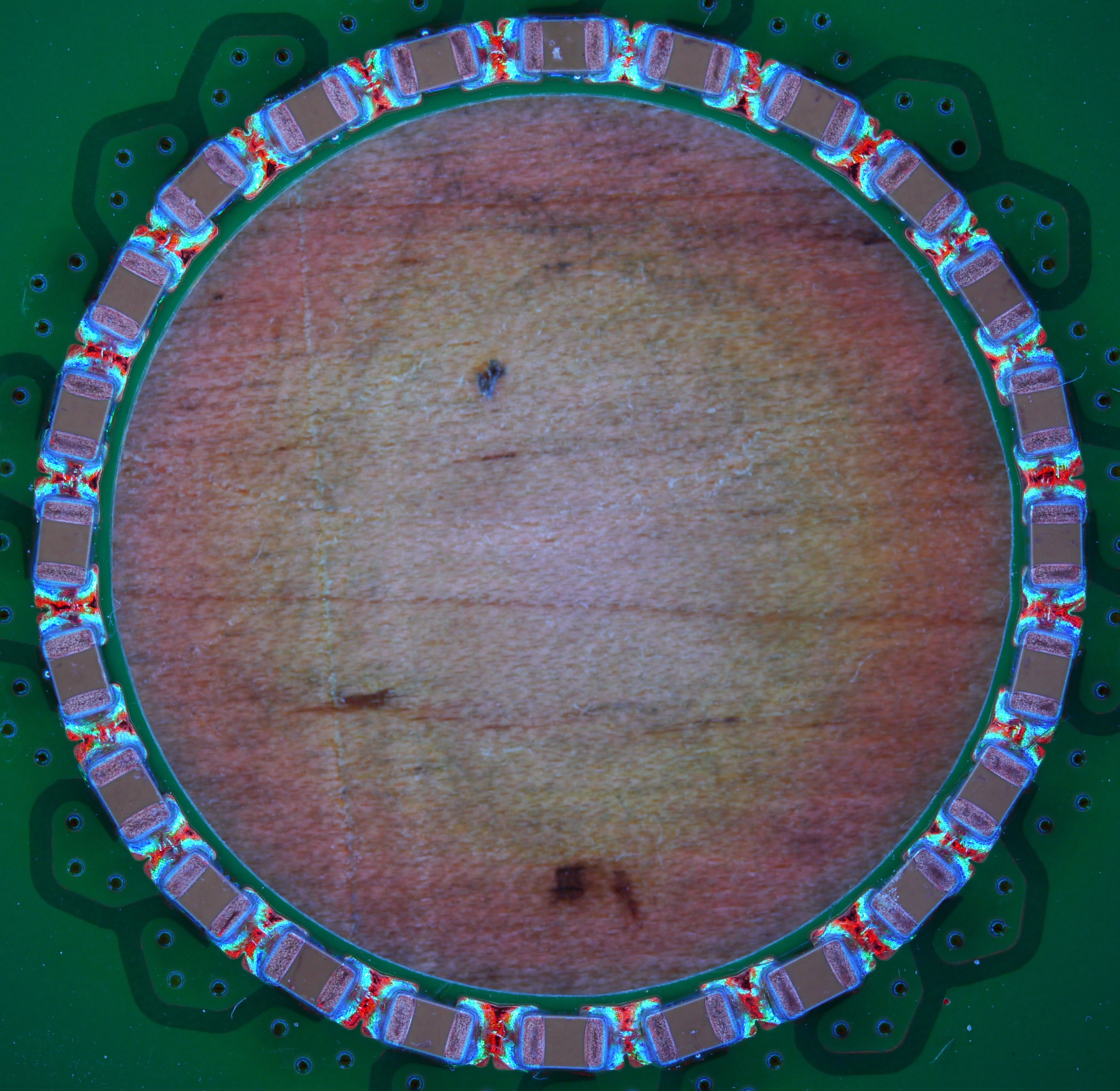
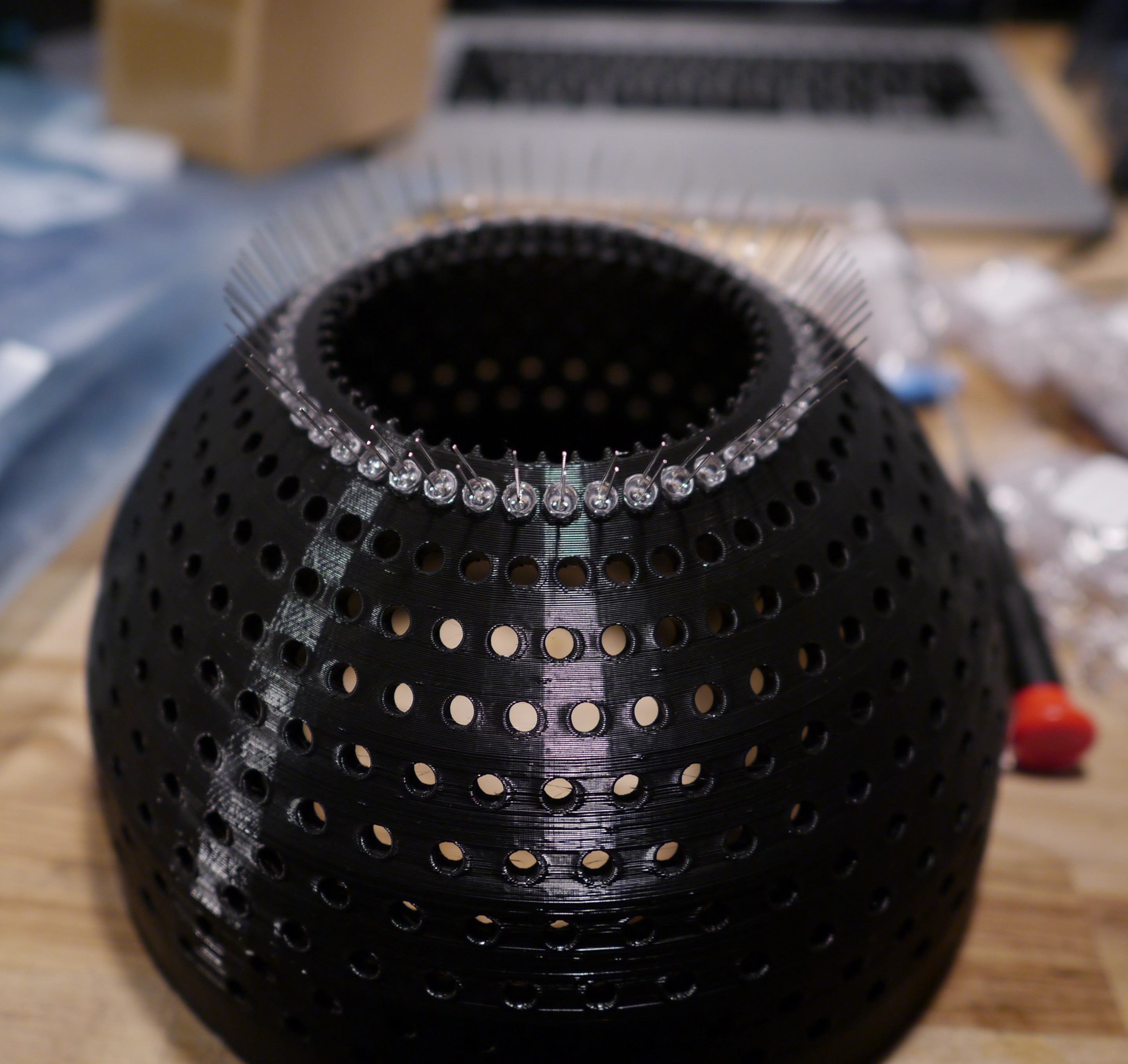
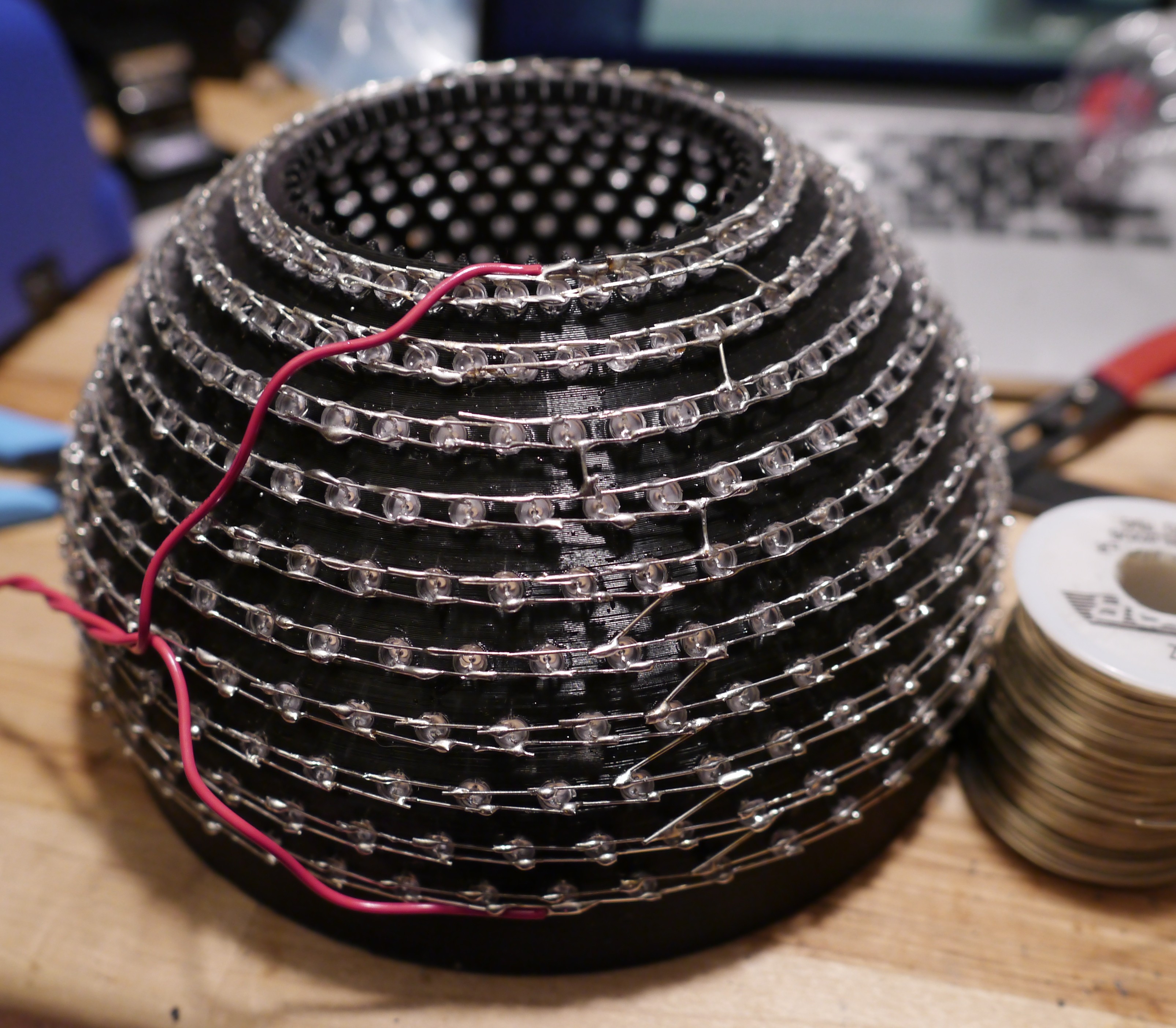
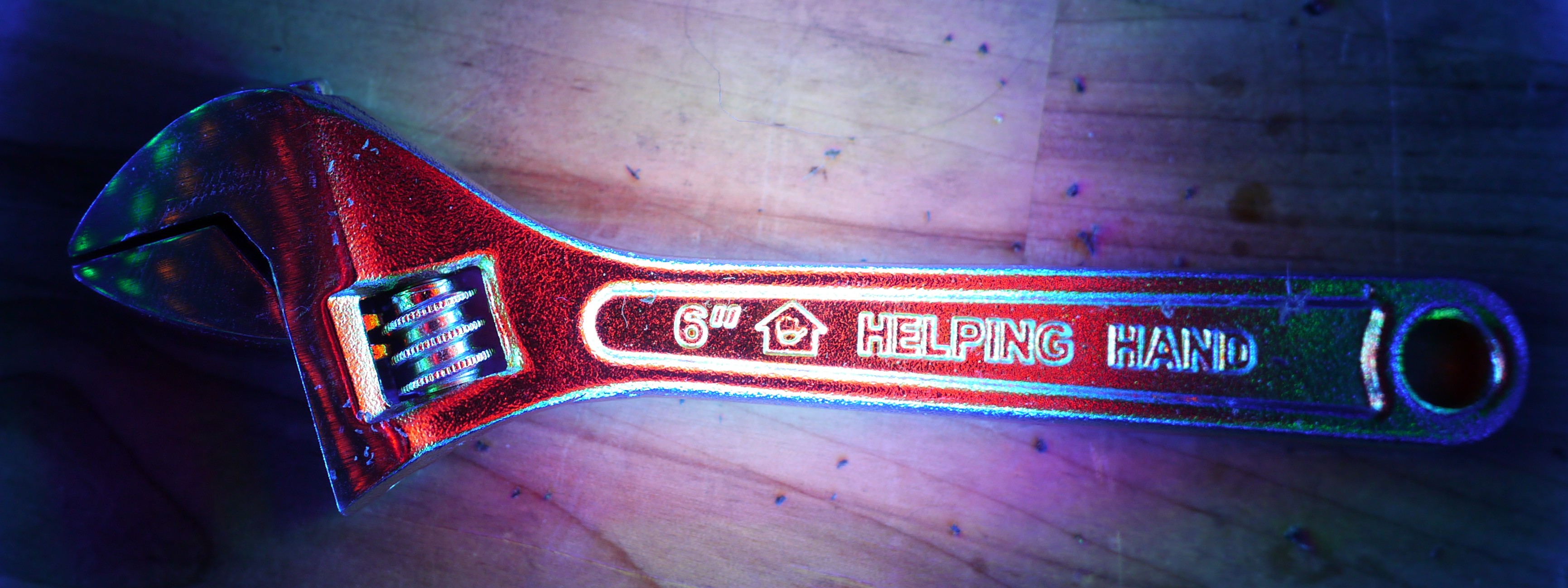
For inserting LED's, place them with the longer lead vertically above the shorter one. Go around the circle of 48 and insert all loosely. Then go back around with a mostly shut crescent wrench or screwdriver and press the LED's in so they're all the way in. Then, take the top lead (anode) and bend it down counterclockwise on the outside of the adjacent LED anode. Go around in a circle. Then, bend the shorter lead (cathode) clockwise to the outside of the adjacent cathode. Bend them so they don't have too much of a gap between them. This is critical for the soldering. You need a bead of solder to wick and stick to both of them so the smaller the gap formed, the better your joint will be.
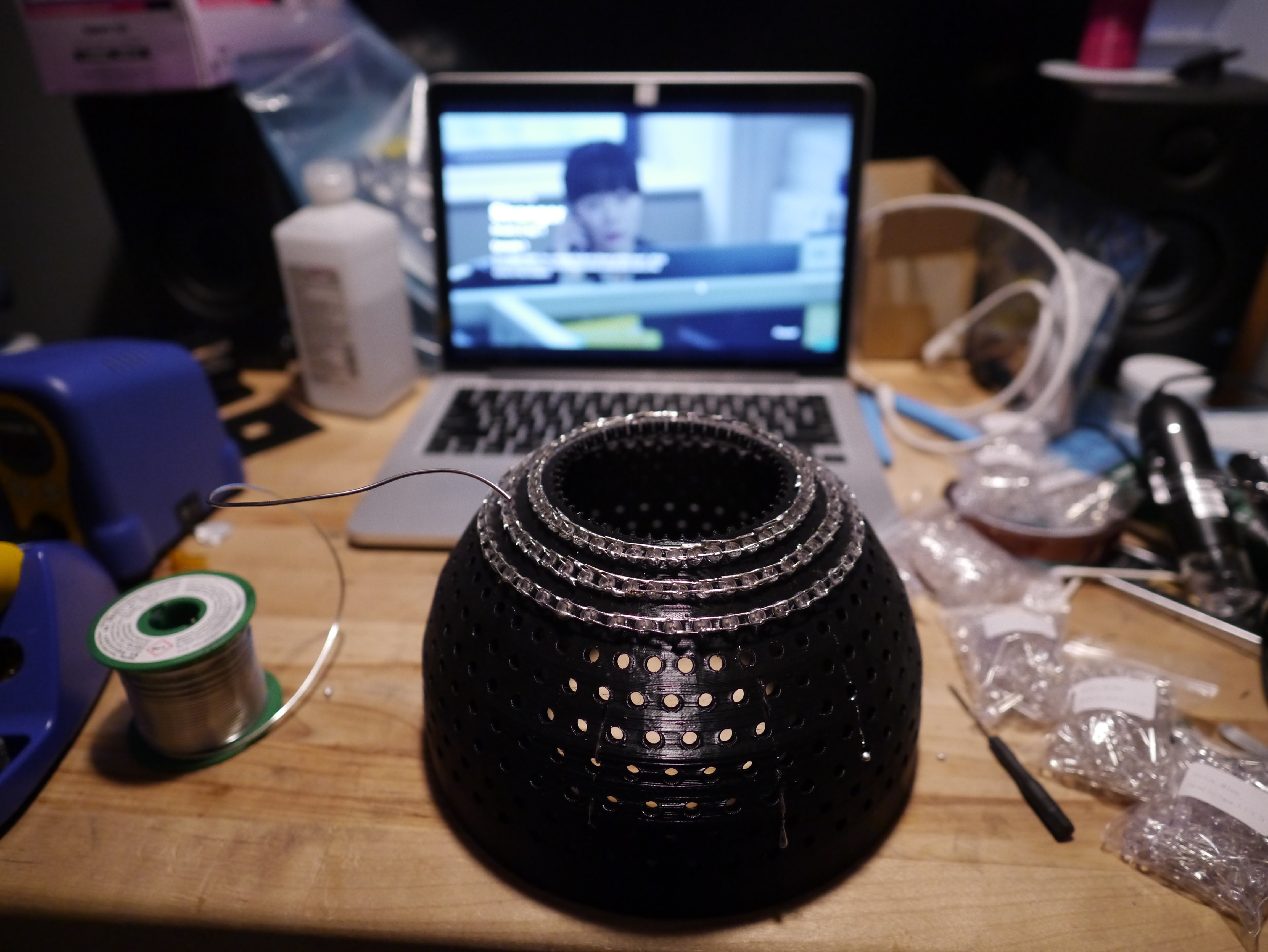
For soldering, you'll want to use a good solder with rosin. I use a Kester SAC (Sn Ag Cu) flux-core solder so the only neurological abnormality I end up with is brain cancer from the fumes instead of brain dumbening from the lead poisoning. I need my remaining 2 brain cells to do stuff. Put some solder on the iron and place it on the leads to be joined. If the gap is sufficient, you can move on. If the gap is greater than 2mm, you'll need to add enough solder to leave a ball clinging on with surface tension to the two leads. It's not the best joint, but you'll need to make 2,000 of them, so just go quickly.
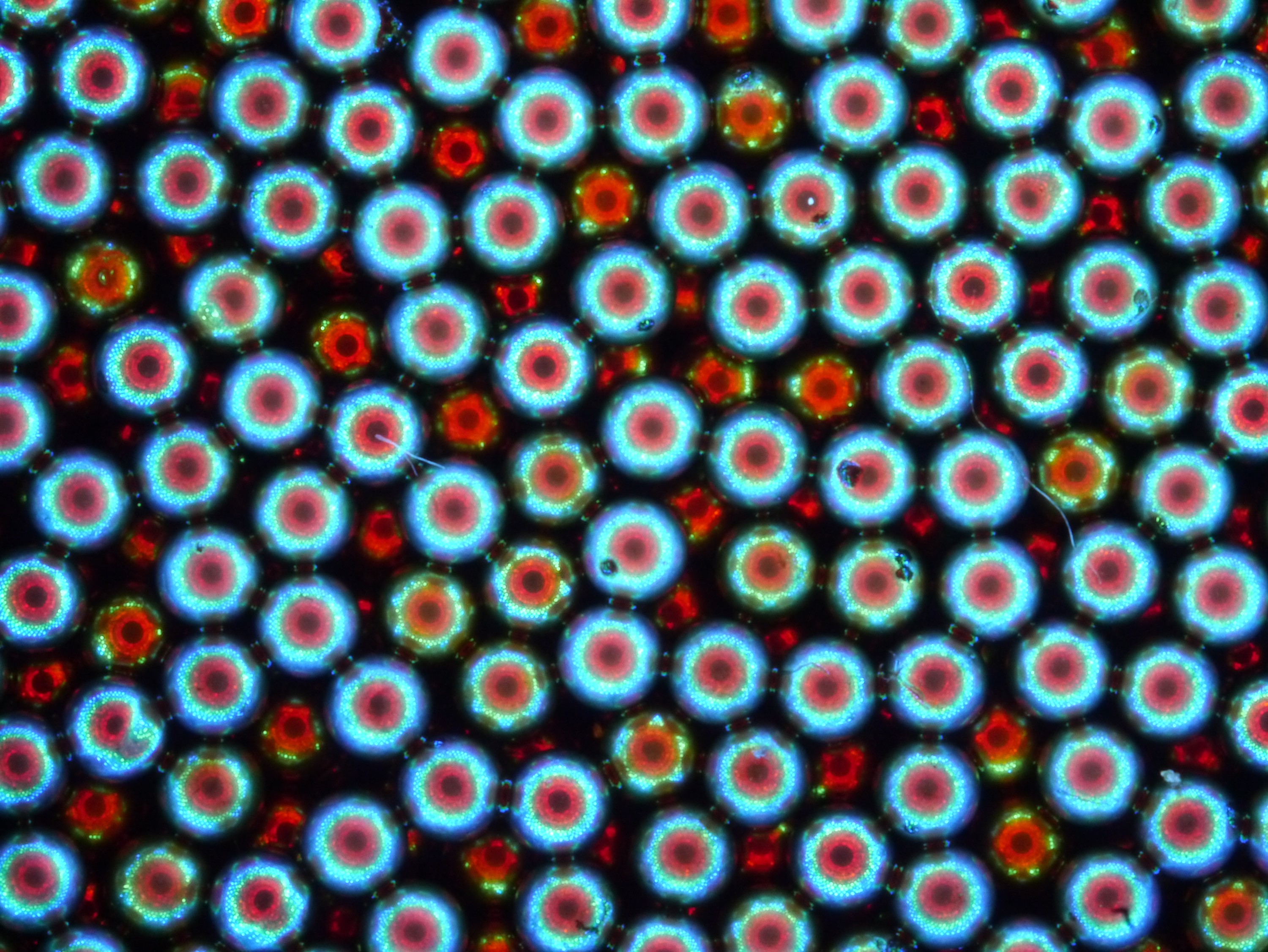
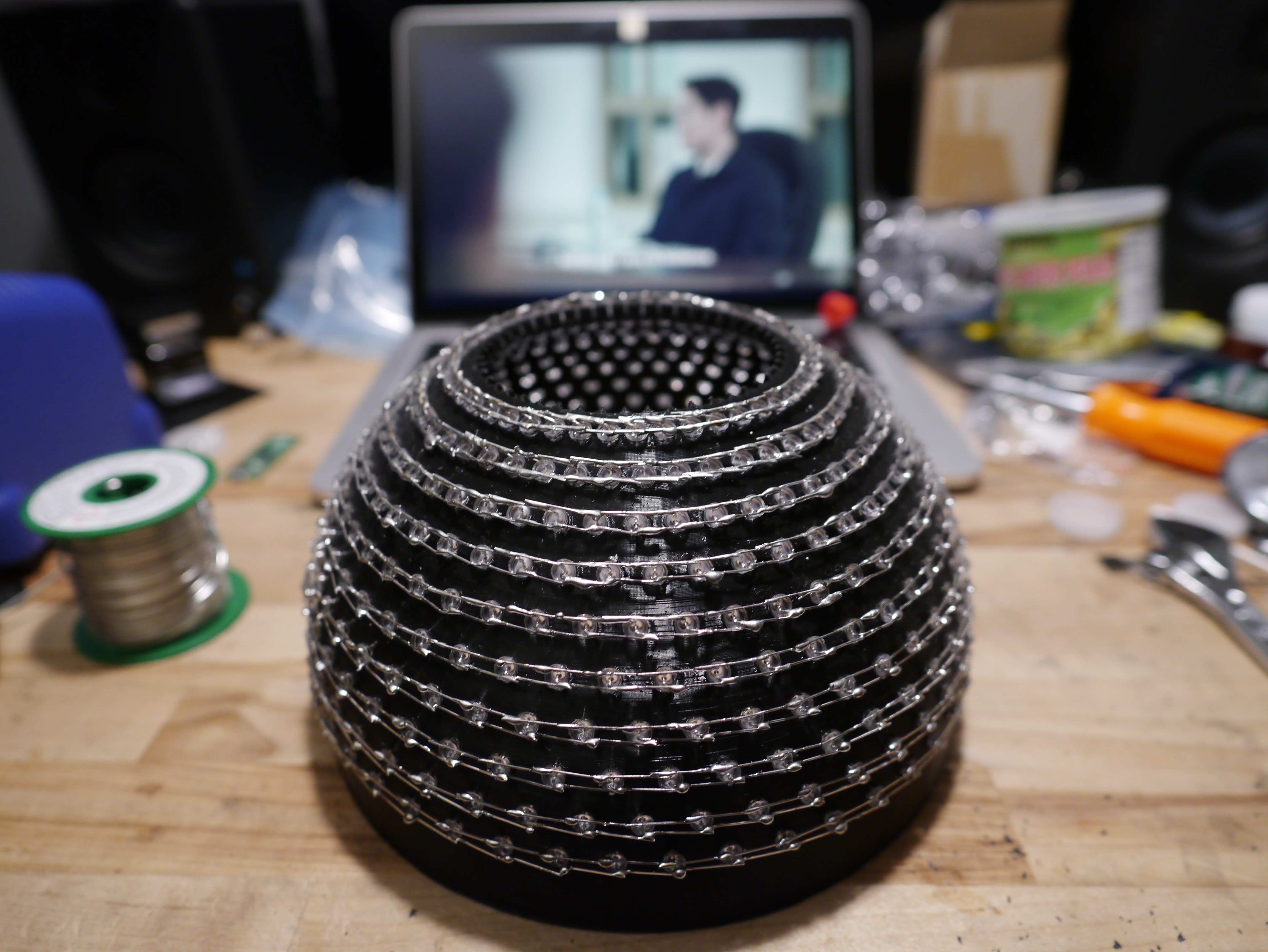
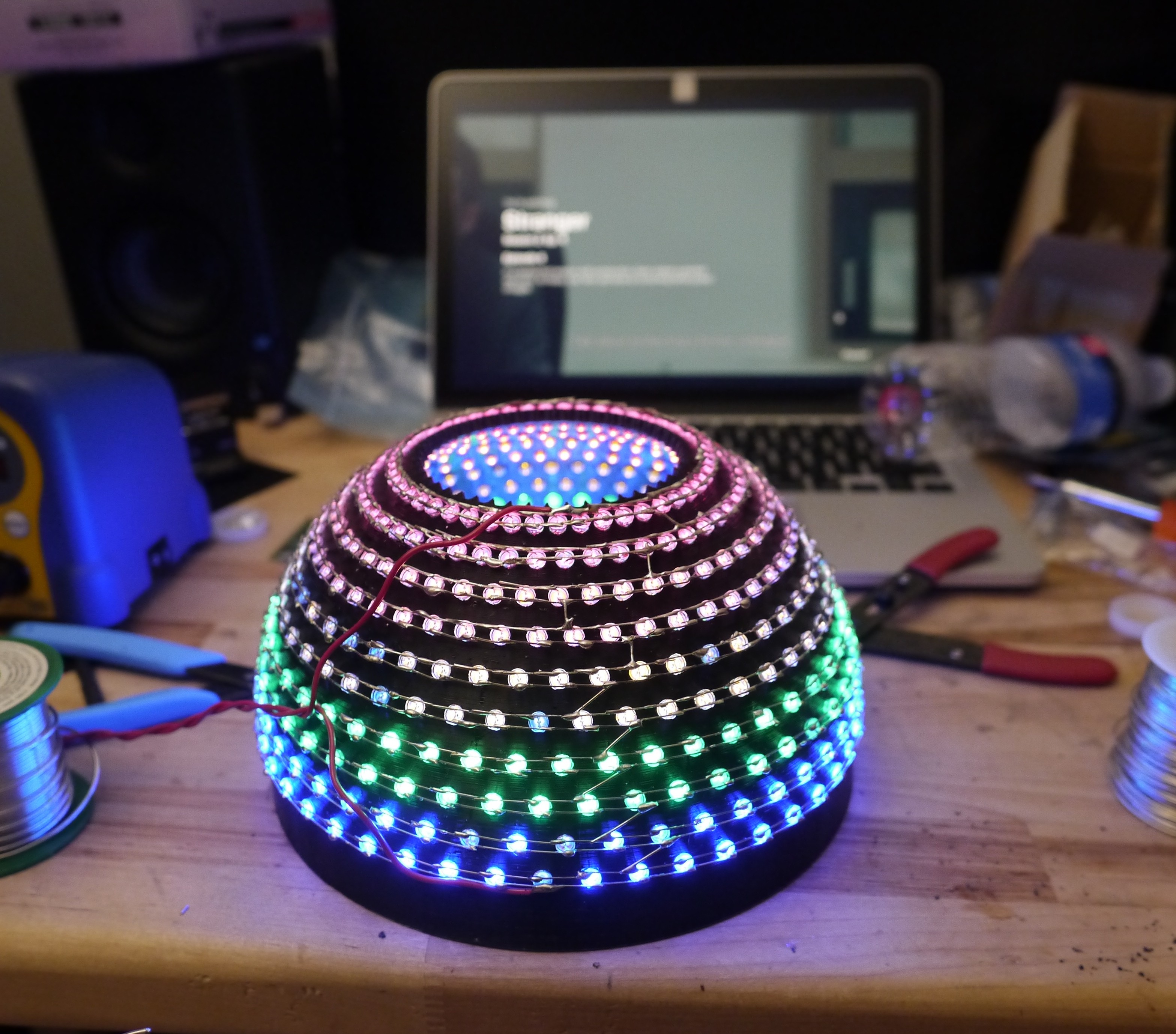
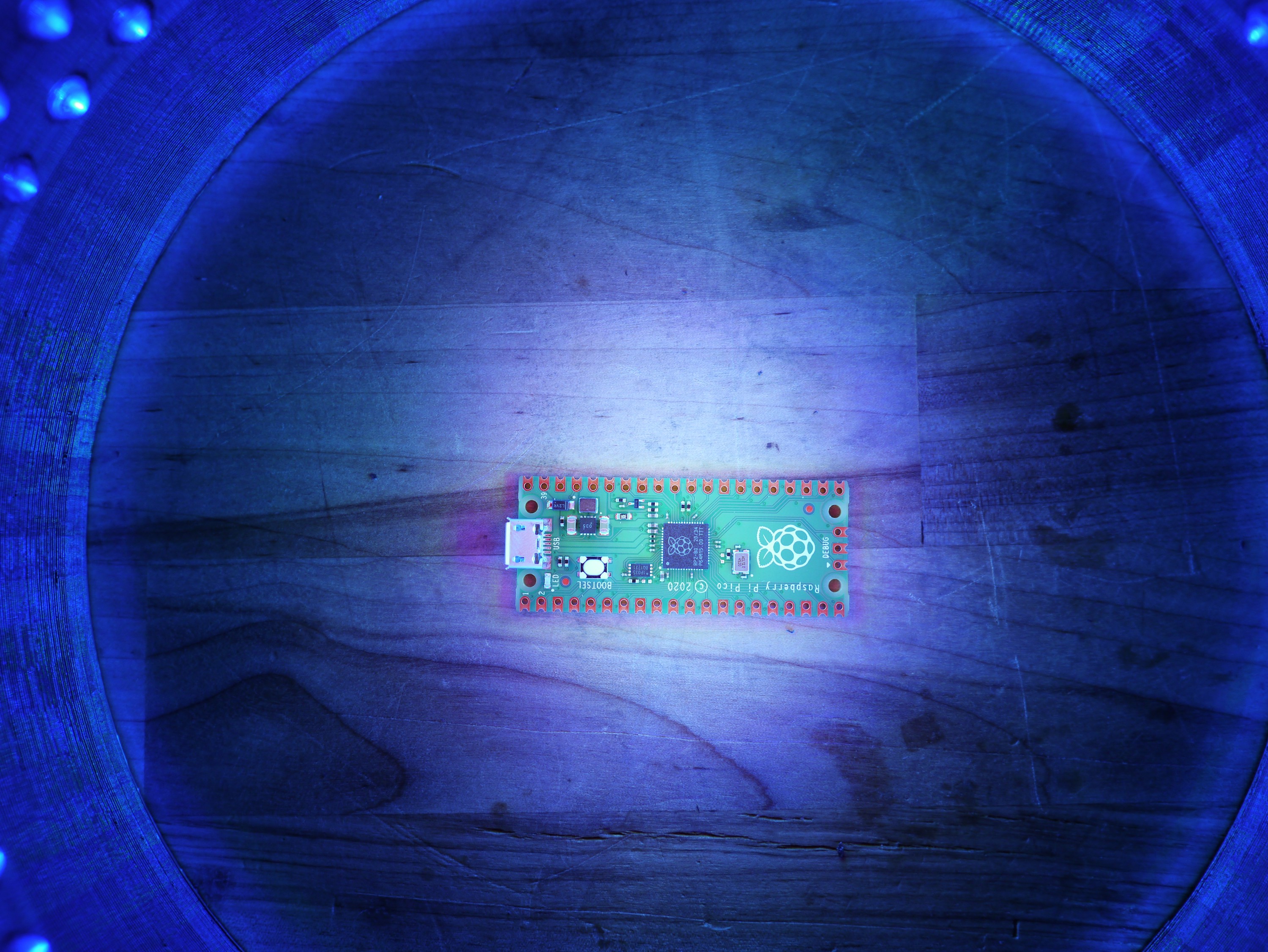
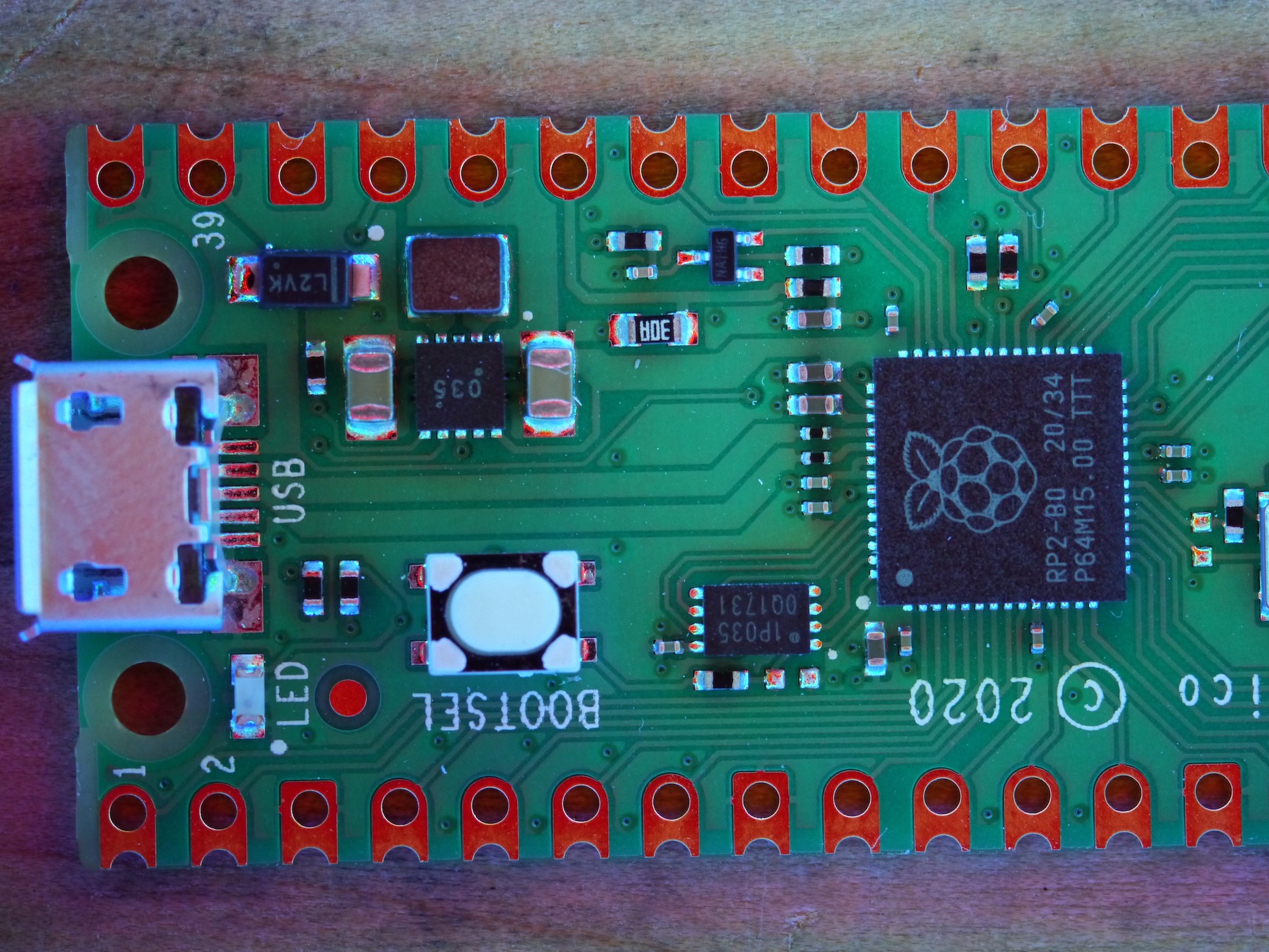
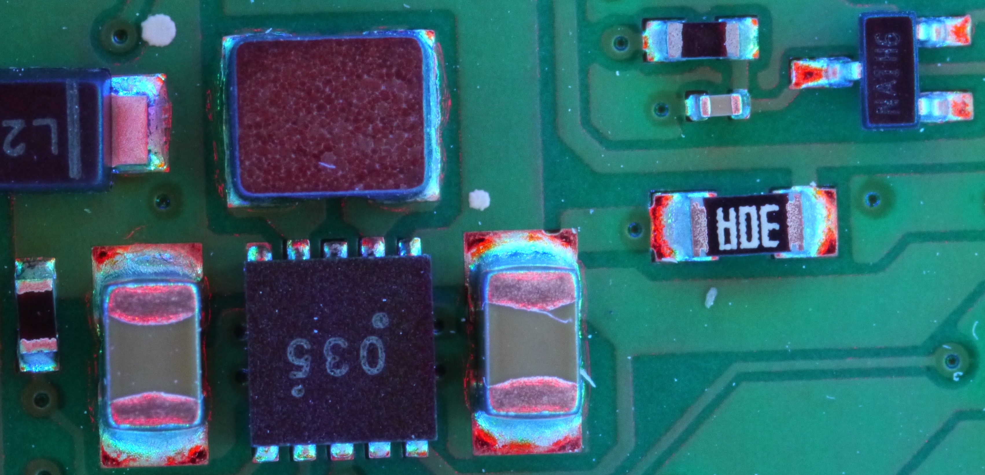
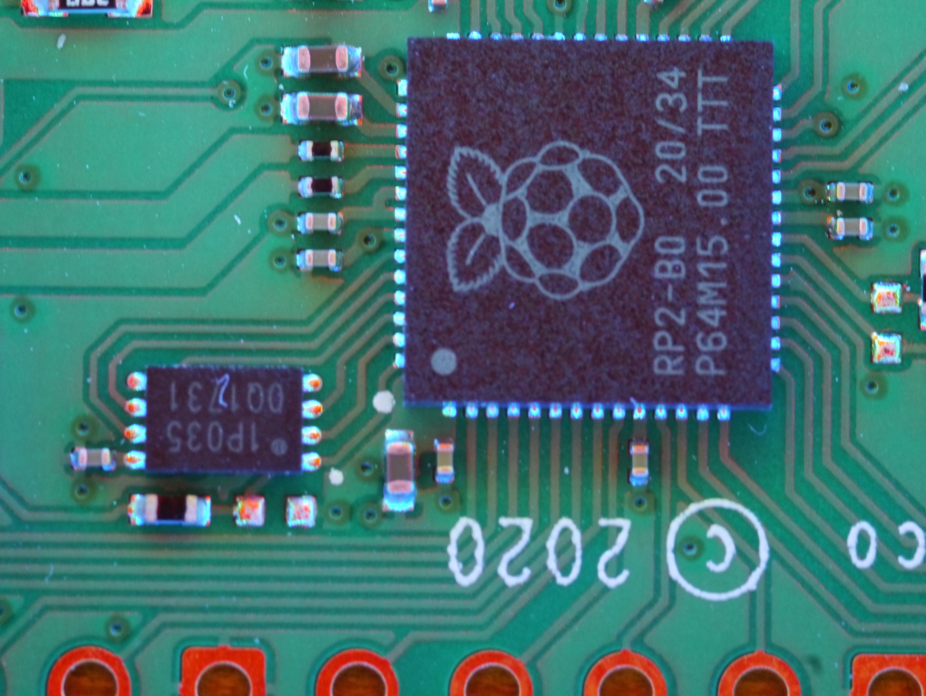
Rinse and repeat until all the rows are done. Commercial AOI lights use an RGB pattern and I used an ROYGB pattern because LGBTQ pride has my favorite color scheme!
Then, you can connect the upper cathodes to the lower anodes to create a series connection of the parallel LED's. In total, my dome took 21V and a few milliamps. I am not risking a burnout by pushing it beyond 10% of the LED's rated output. It's just not worth it!
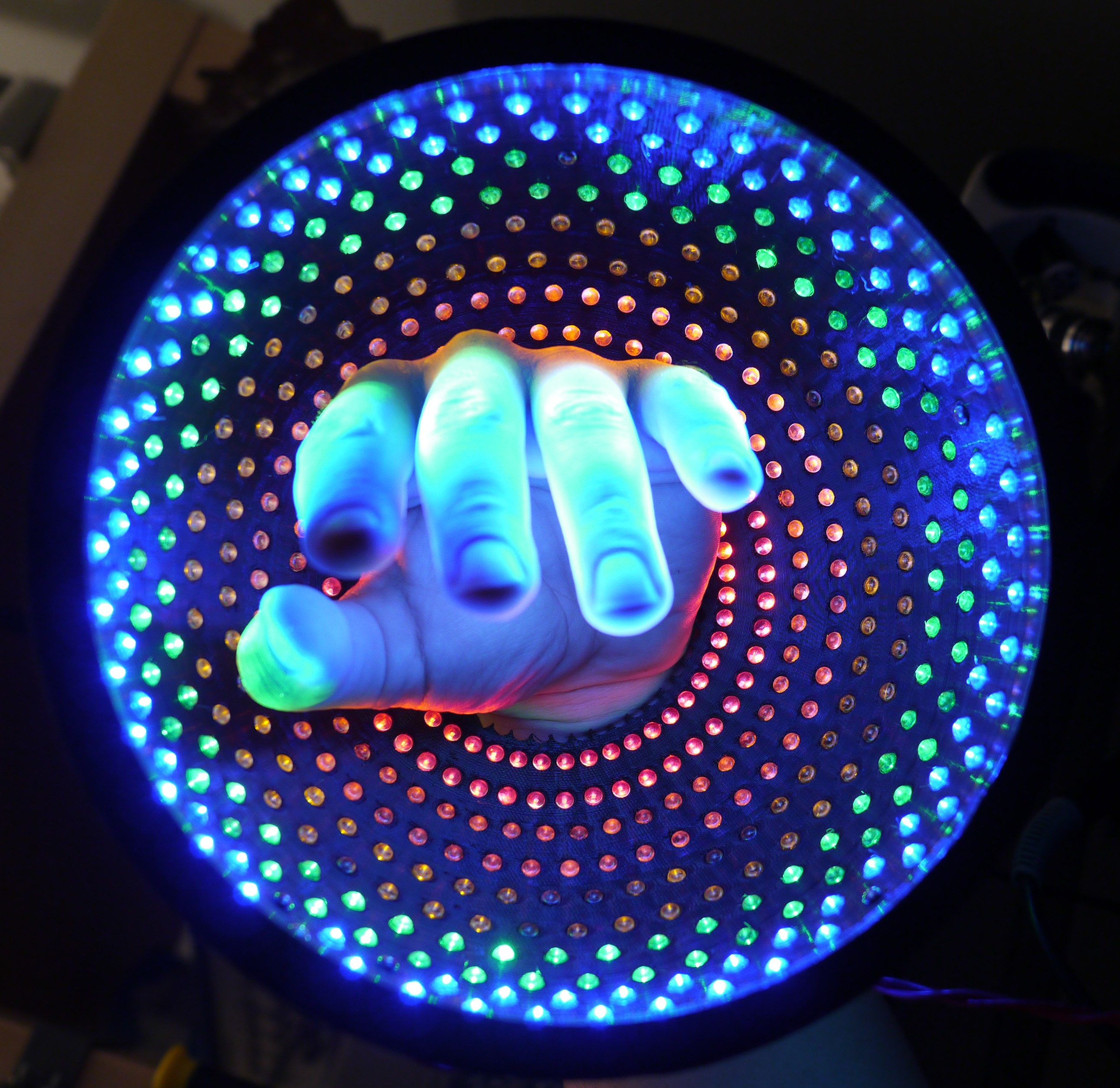
Enjoy your shots!


 Andy from Workshopshed
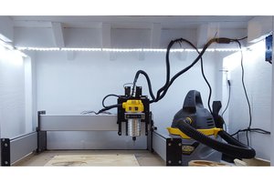
 Alex Rich
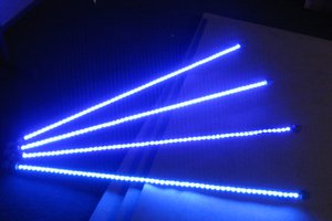
 Ian Norton
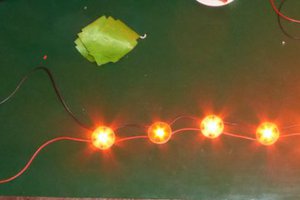
 Joseph Eoff
Great Project! You missed one! (photo of wires connected) but that gave me the idea, use last pin in loop for jumper wire.