 Sina Roughani
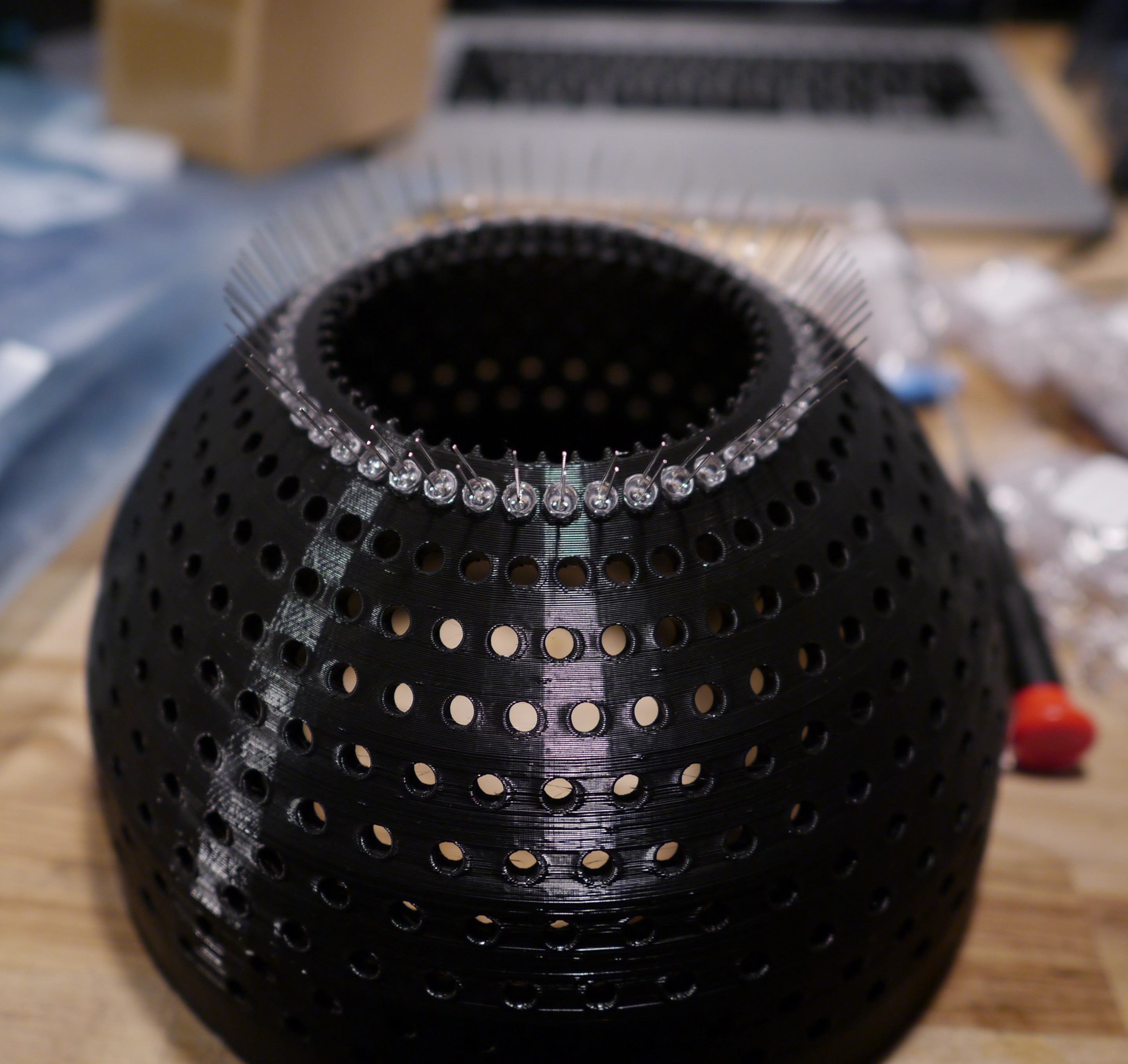
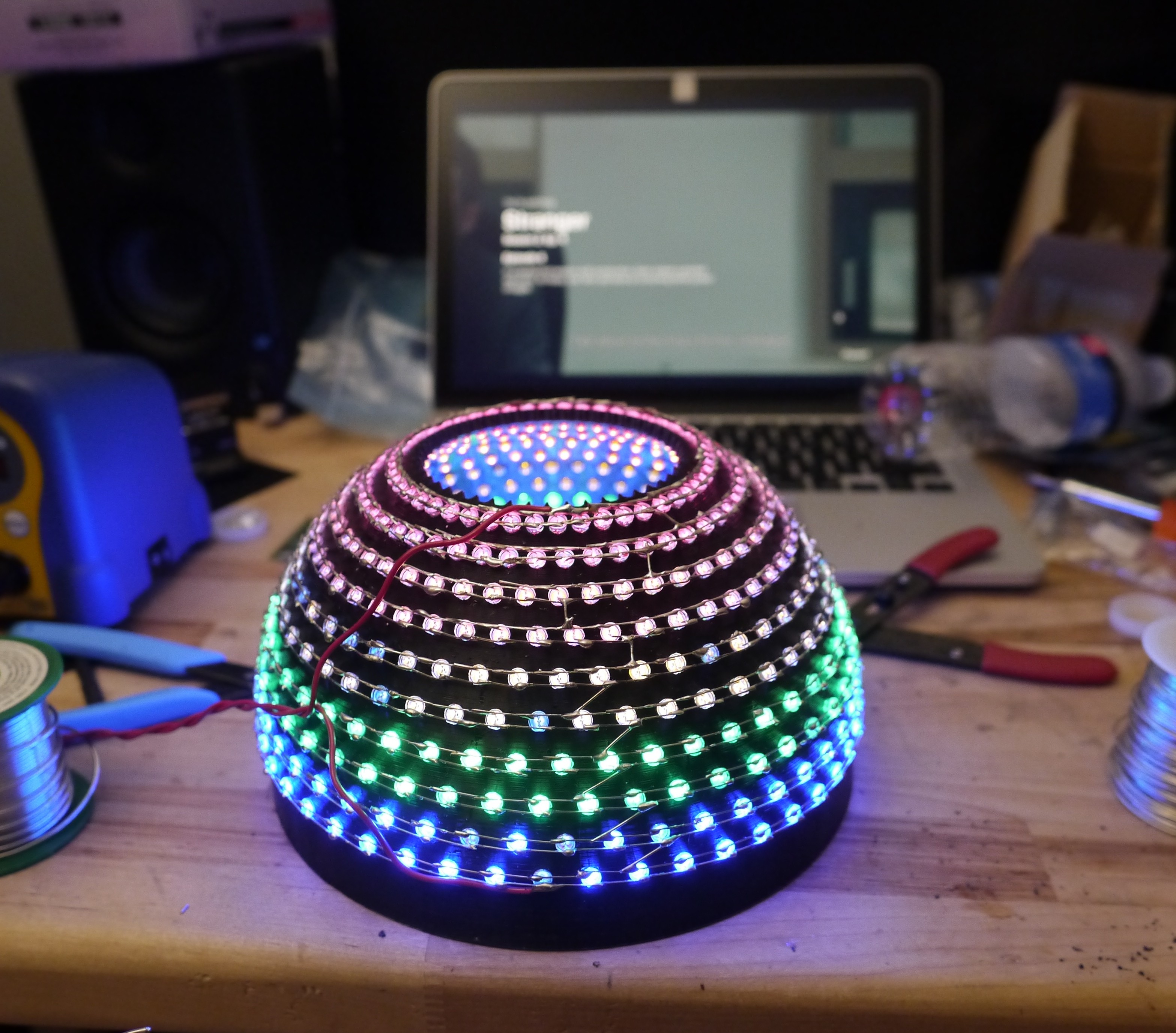
After a few days of sore fingers, I just went for it. The holes were so tight that it was a real effort to push the LED's in. But, I just pushed them in using a crescent wrench to get even pressure on the back. Here's the first row inserted with cathodes below anodes.
A few rows inserted and soldered...
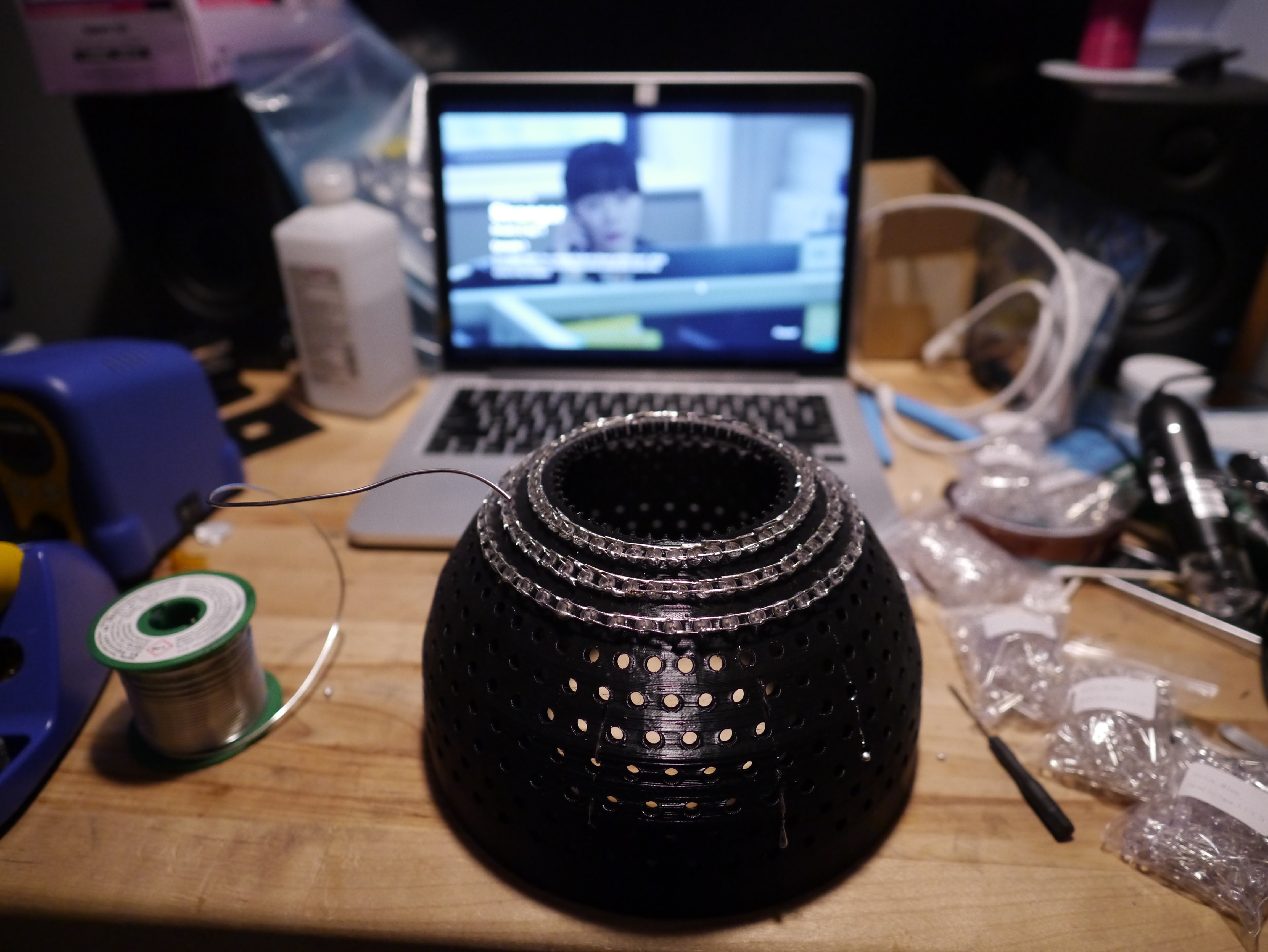
The show "Stranger" on Netflix is pretty good. You should check it out.
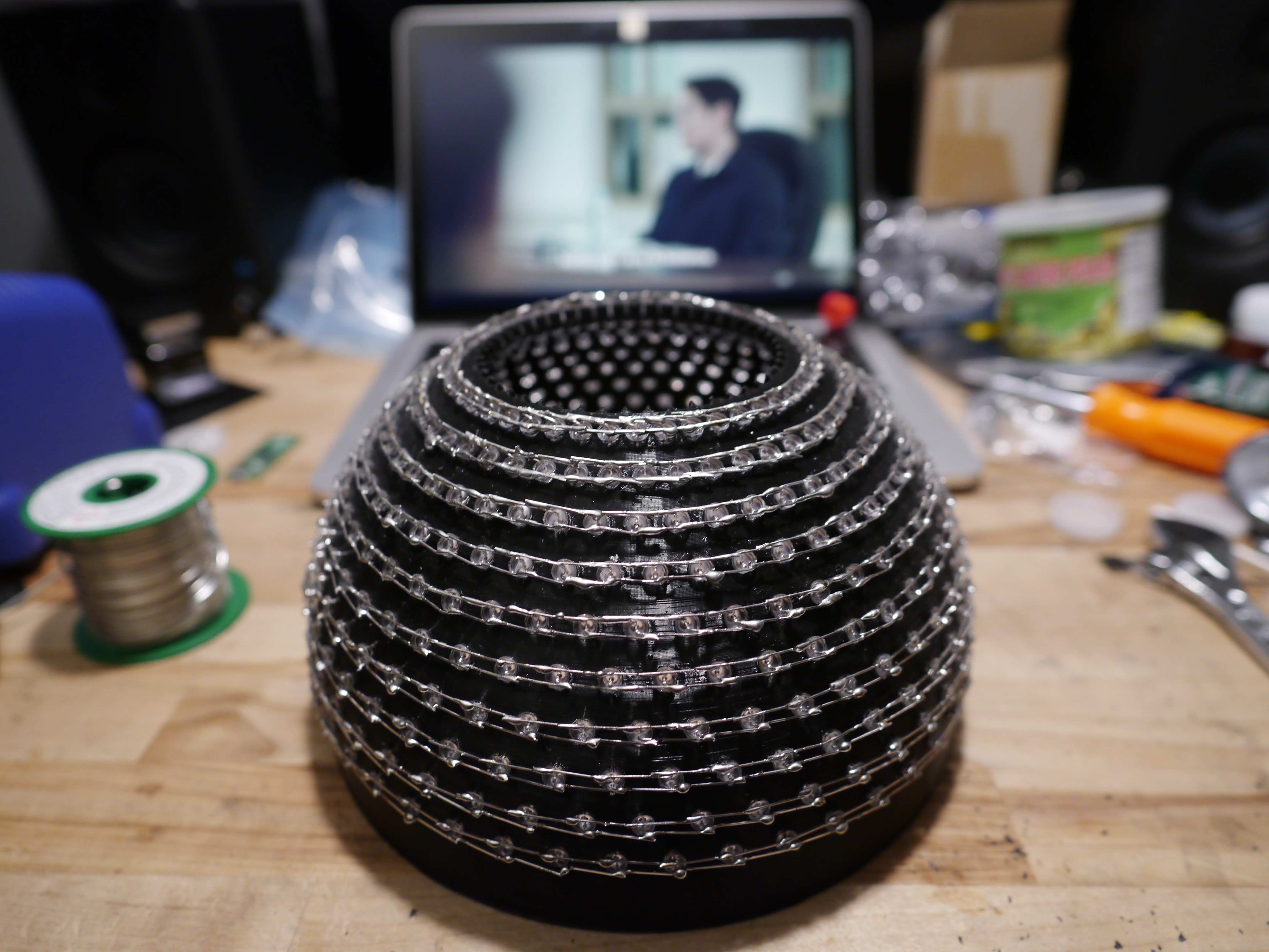
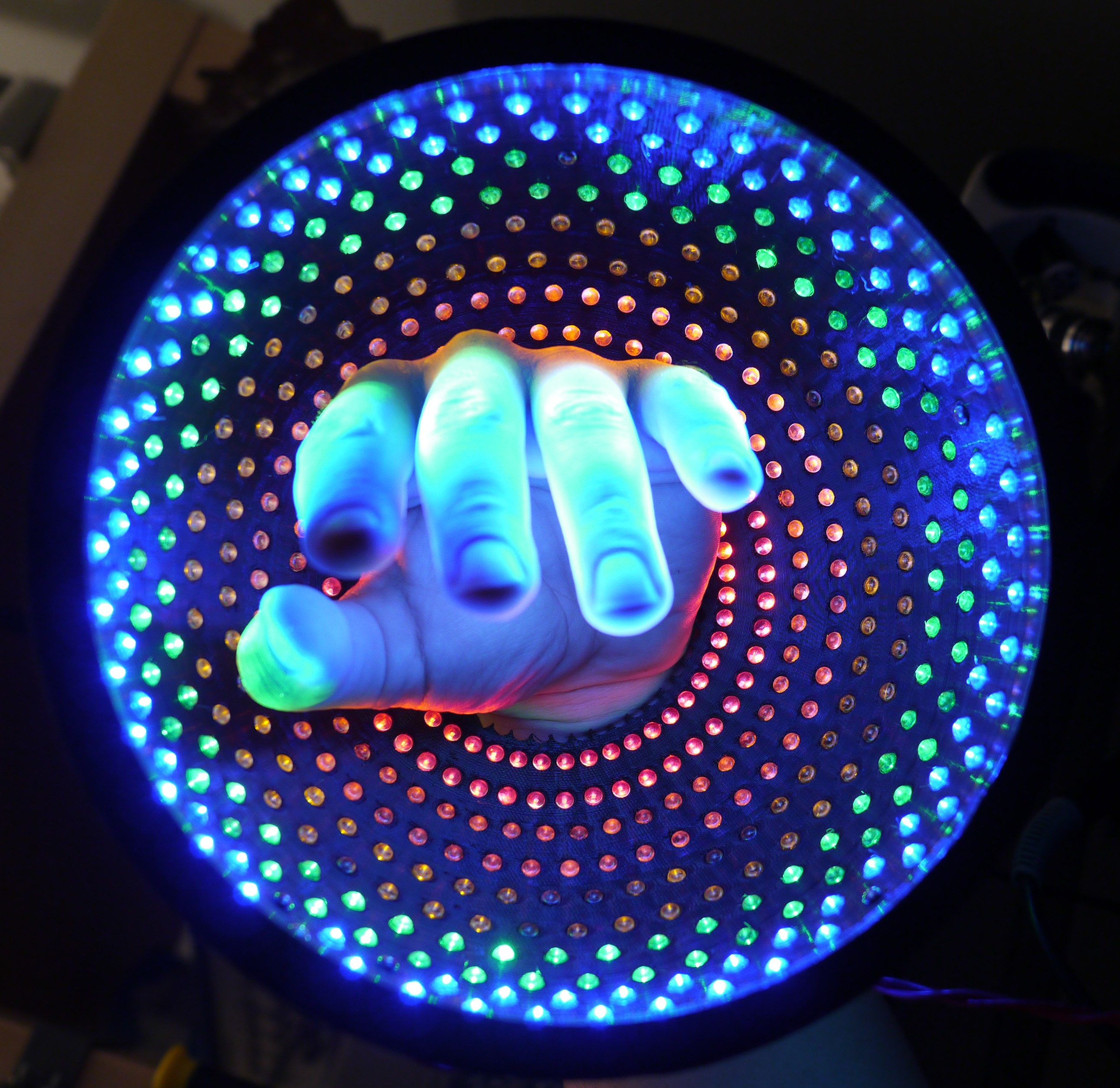
After a few episodes, I was done!
Then, the serial connection
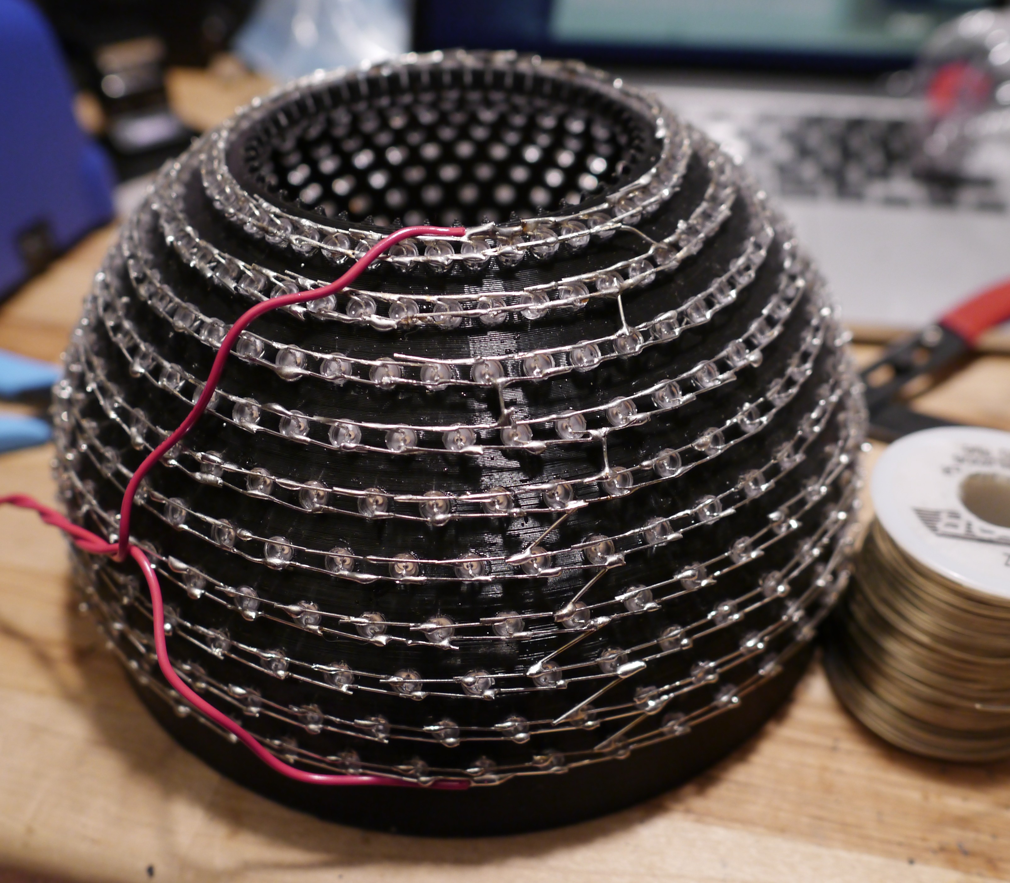
And with the power supply carefully applying 21V,
Imagine waking up to this, lol
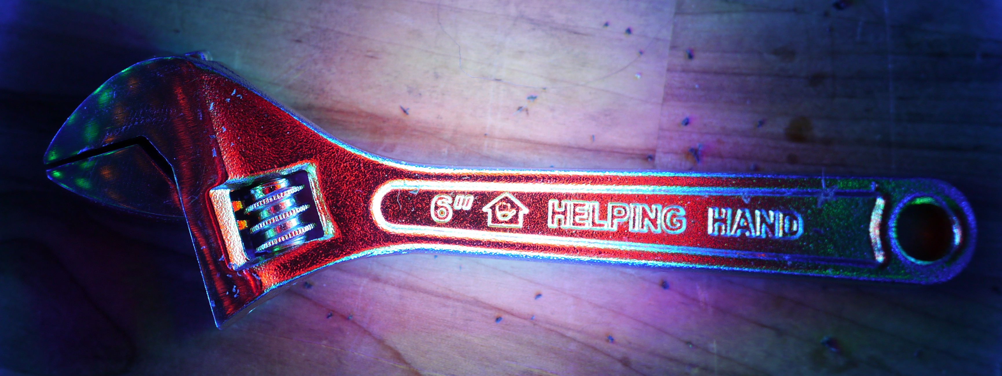
Okay, but here's the helping hand that helped me push all those LED's in place.
And let's pick something popular to test this out with... hmmm...
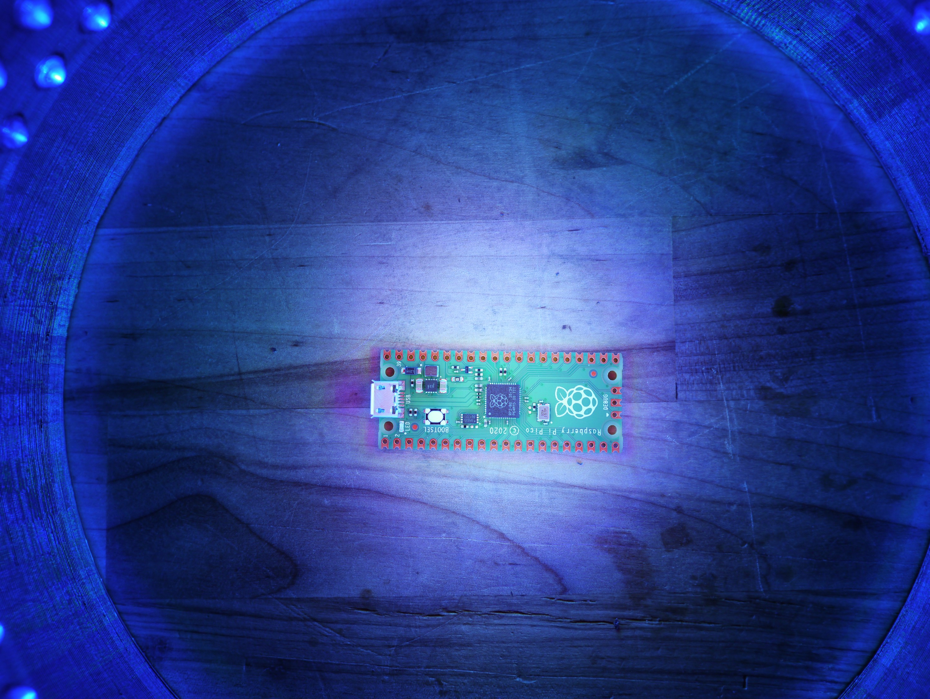
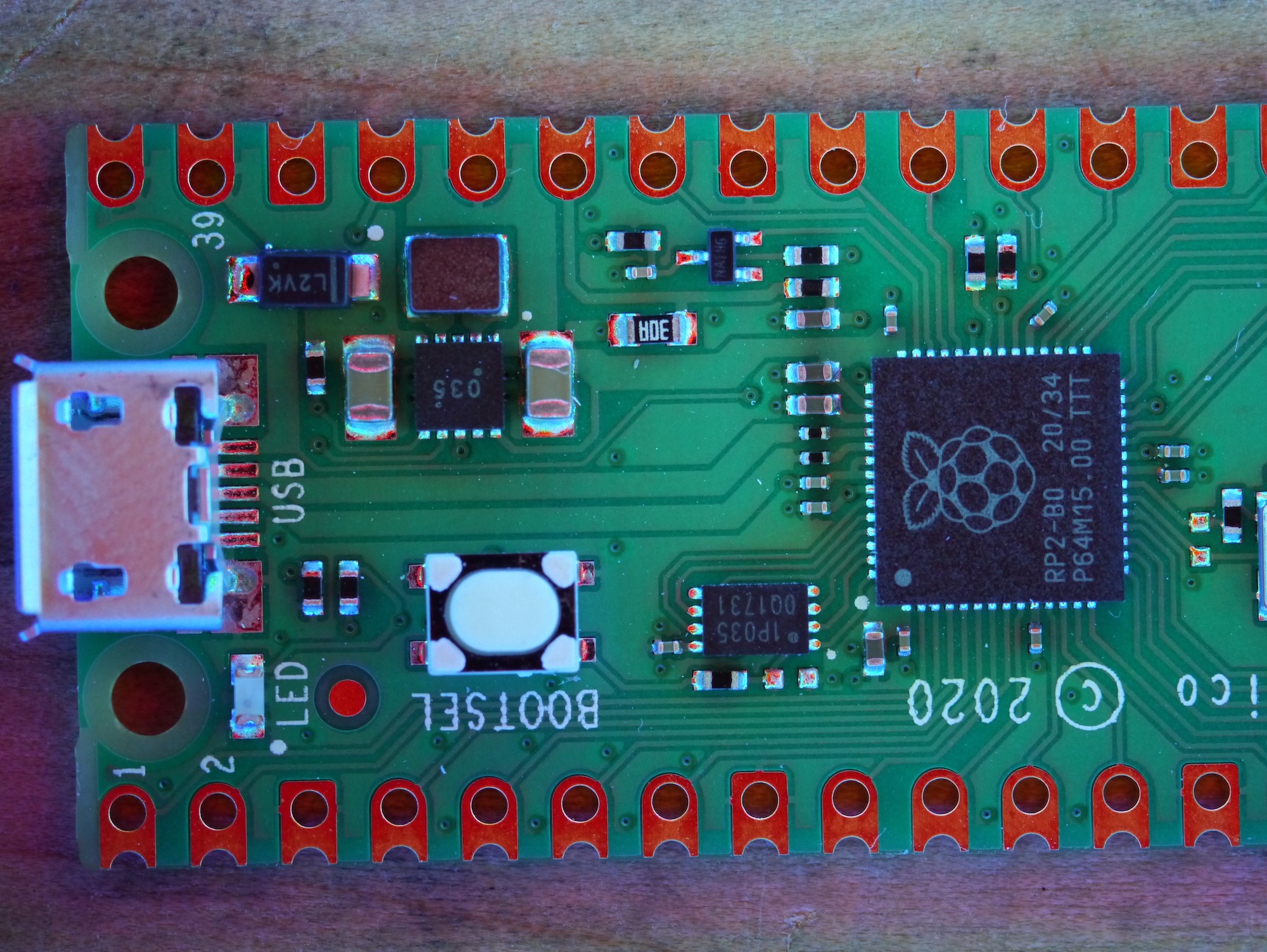
Let's check out some of these joints.
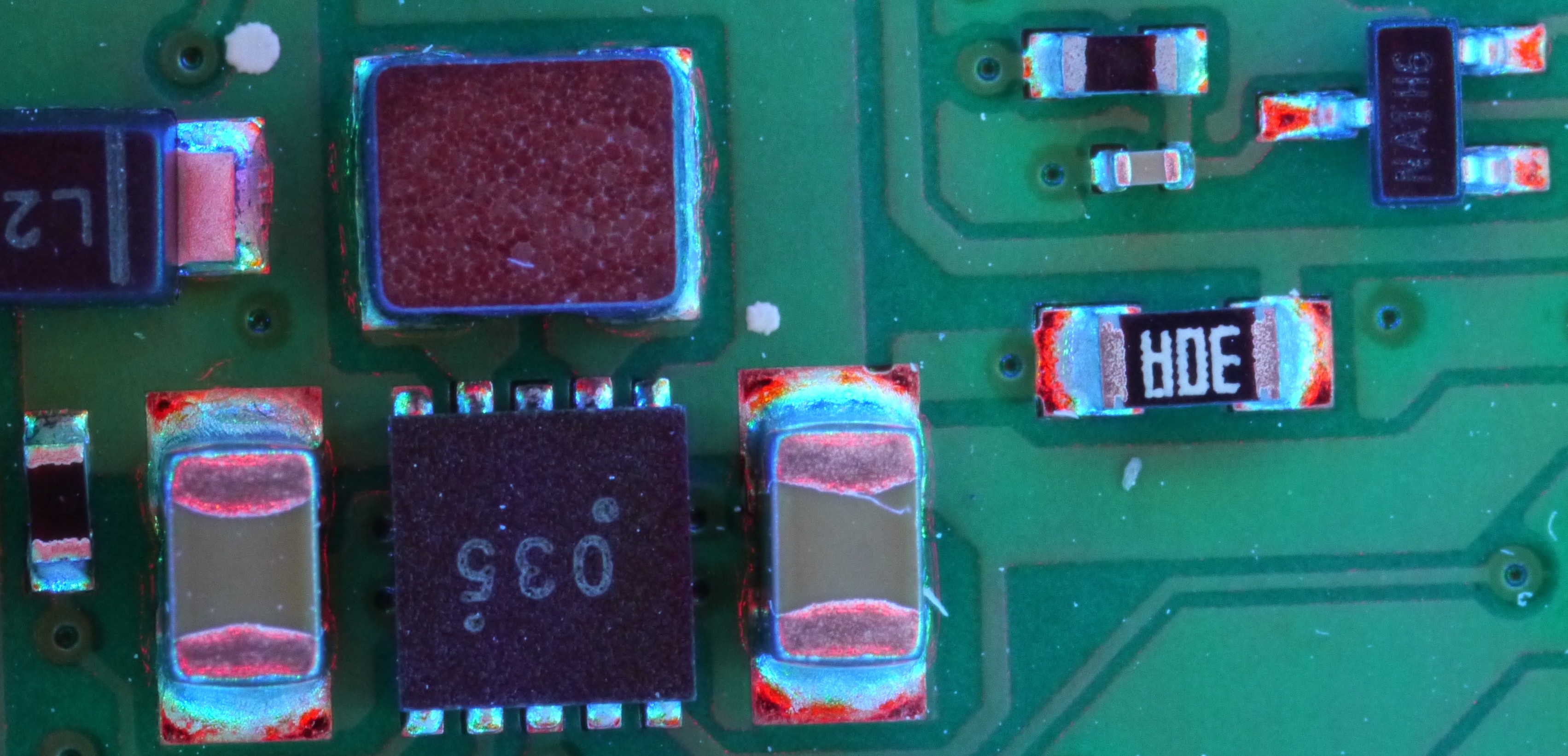
If you look at the SOT package on the upper right (3 leads), you can see the smooth rainbow transition due to the long pad transition area. The same applies to the resistors and capacitors. However, the DFN package marked "035" has uneven lead formation. Specifically, notice how the fillet on the upper middle pin is radiused instead of filleted like the adjacent pads because the adjacent pads were able to use the traces leading to the inductor to wick into the pad. Alternatively, the inductor could just be blocking the light and not showing a smooth fillet.
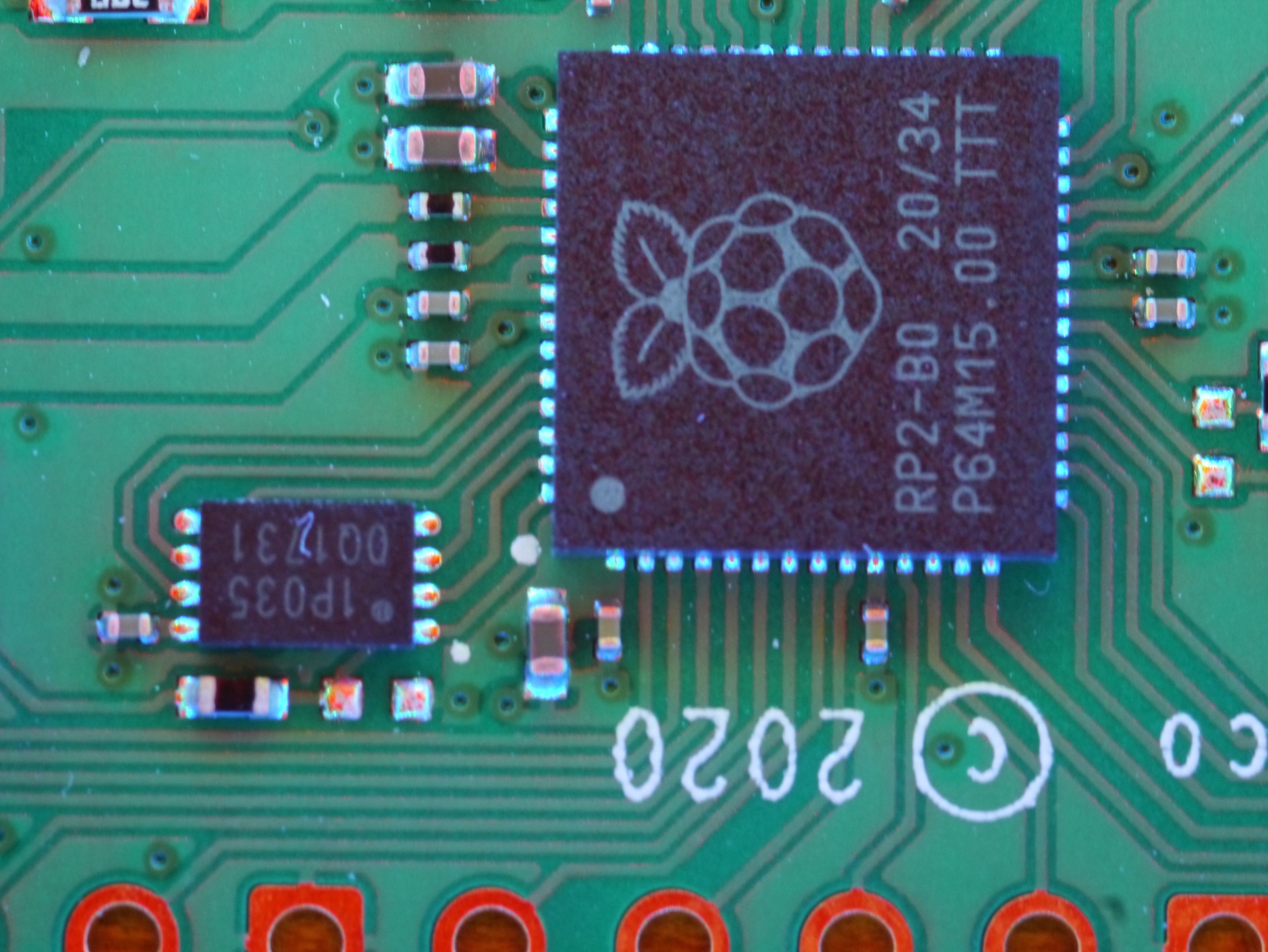
On the DFN ROM chip, you can see uniform, well formed joints. The light produces an interesting glow. You can even make out the lighting variations on the copper and soldermask thickness variations as well. It's a very fun lighting process!
Hope this inspires you!
-Sina
Discussions
Become a Hackaday.io Member
Create an account to leave a comment. Already have an account? Log In.