 ronald.sutherland
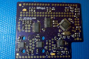
Basically, the RPUadpt serial can be configured as a point to point (e.g. host to bootloader) or point to multipoint (e.g. host to multidrop) with I2C commands from either a connected SBC host or the RPU controller board it is mounted on. An SBC with I2C/SMBus can then compile the source code and bootload an RPUno selected with the I2C commands without exposing any upload interfaces on the network. The uplink to the internet can be intermittent (or down) while doing the software updates and debugging if the developer is at the local network.
Update: ^6 adds IOFF buffers to the UART that allows the host to power off without locking up the interfaces (i.e. another host can use the serial). SPI interface has host interface with IOFF buffers and CS (to nSS). 328pb adds a second I2C port so the SBC host can use it with SMBus, and when the host is powered down it will not block the RPUno from using its I2C.


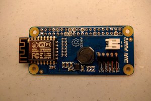
 ajlitt
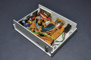
 Dilshan Jayakody
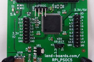
 land-boards.com