 mircemk
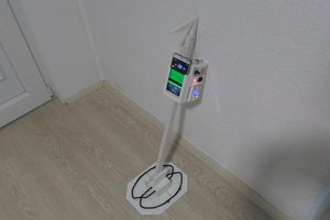
Presented device is based on an acoustic transducer and a reflector. The main component of the levitator is the transducer, element that transform the electrical input signal into ultrasonic acoustic waves.
In this case, this is 60W transduser with resonant frequency of 40 KHz which I bought for about 15 Dollars. Levitator is driven with a sinusoidal excitation signal to generate a standing wave between his elements; this standing wave will trap particles at its nodes.
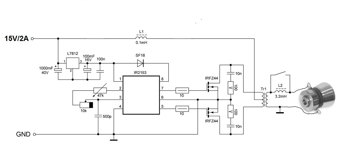
The device generally consists of a power source, a sinusoidal signal generator with a certain frequency and an ultrasonic transducer. As we can see, the electrical circuit of the device is relatively simple and consists of IR2153 SELF-OSCILLATING HALF-BRIDGE DRIVER, two power mosfets, stabilizer for 12 volts and several resistors and capacitors. There is also a high frequency transformer that is taken from an old computer power supply. And now a little clarification about the transformer. One side contains only two contacts and here is connected the transducer. The other side contains multiple contacts of which the thickest wire always represents the middle pin. The other two ends need to be determined experimentally, but in my case both transformers I found were identical and connected as in the picture. This can be seen more precisely in the description in the video.
As seen on the oscilloscope, the signal of the mosfet gates is rectangular, while the output signal going to the transducer is almost sinusoidal. The frequency is around 40 KHz.
The distance between transducer and reflector must be exactly right to create a standing wave with sufficiently strong regions of high and low air pressure. We can estimate the distance using the formula, based on the speed of sound at room temperature and resonant frequency of transducer:
343,000mm/sec / 40,000Hz = 8.575mm
In our case distance is 8.5mm or a multiple of that value. So there are more such points that we can determine experimentally.

 Electroniclovers123
 tshen2
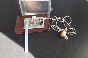
 Andrea Console
a reference: https://www.makerfabs.com/acoustic-levitator.html