As I'm already 1.5 years into this project, but missed to write anything up, this is a mix of an overview on the project and a mostly chronological log.
Some Design choices
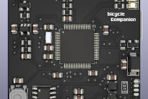
As I most often use ATMega uCs in my projects, I decided to stick to that here as well.
As the 96x96px Sharp Memory-LCDs are not in production anymore, I use the newer LS013B7DH03 128x128px display. This means I need some RAM for the framebuffer. Thus the choice of the ATMega 1284P as uC.
As my analog design-skills are limited (and RF skills practically non existent), I decided to use an integrated module, the Microchip RN4871, that also brings some certification. That of course means this watch will never reach a power consumption as low as an NRF or STM32 standalone solution with integrated radio would allow. However, a couple of days of runtime should be OK, and it's still a learning project.
The RN4871 cannot be used with the maximum of 4.2V expected from the Li-Ion cell, hence a 3.3V regulator is needed. Also, according to the datasheet the ATMega is not guaranteed to run stable at 16MHz and 3V. However, I need to be able to communicate with 115200 baud to the RN4871. Hence, the main clock frequency of choice is 7.3728 MHz allowing for no baud rate error at 115200 baud and stable uC operation.
The main sensors are provided by an LSM303 (magnetometer, accelerometer).
First (round) version
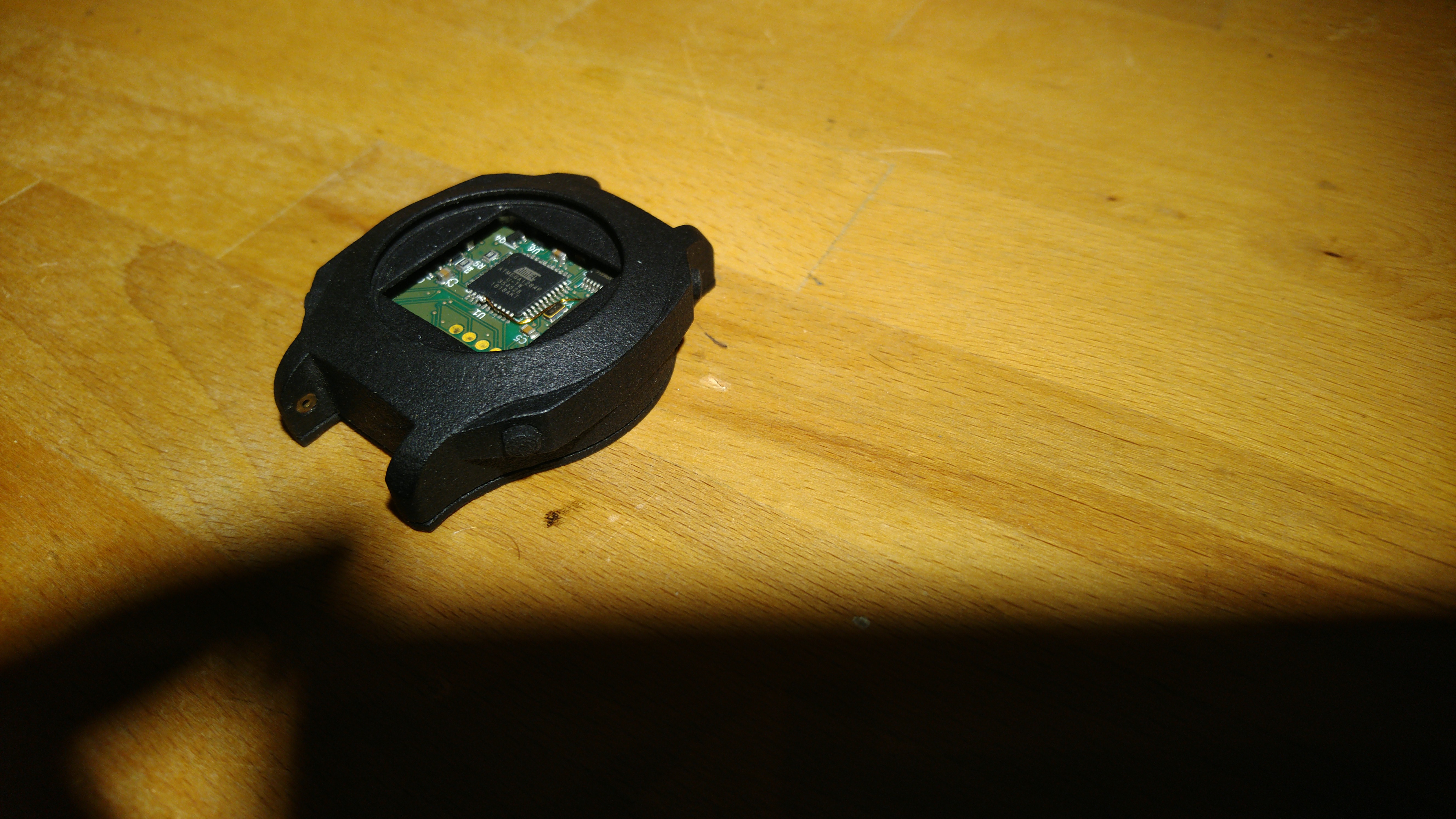
As I do not like rectangular watches too much, the first version was designed as a round watch with an outer case diameter of 46mm (yes, uff quite large). I liked Max.k's idea of using coin cells as you can get replacements everywhere, but due to the higher consumption I decided to use a quite large rechargeable LIR2450 lithium ion cell. Due to the respective coin cell socket this lead to a pretty large 17mm body height. So this design was very unhandy as a watch, but left enough place to fiddle around and fix mistakes I made in the first design.
The case was 3D printed with HP Multi-Jet Fusion (means I ordered it instead of printing it myself). My FDM printer doesn't allow for sufficient surface quality on the overhangs. The buttons, back cover and glass are sealed with o-rings. The o-ring is also what keeps the glass in place. (The above image doesn't show glass and display as I already scavenged those for the second version). Arguably, o-rings don't really seal on a rough 3D-printed surface, but it's better than nothing. From a mechanical point of view this worked great. The buttons were easy to push and you needed serious force to press the glass out of the case. Only the back was a little too thin to provide sufficient pressure on the o-ring all around the circumference, but the missing pressure was supplied by the arm while wearing.
Programming and charging are both done via a waterproof micro usb connector (which is also quite large).
As a backlight I found the integrated modules by FLEx lighting to be the easiest option (FLEx lighting 11049-03).
In order to keep the BOM short I thought I'd stick to the internal RC-oscillator as main clock for the uC (not for time keeping). This means the RC oscillator is calibrated to approx. 7.3728 MHz on each boot based on the 32kHz clock crystal on Timer2 (PDF ATMEL AppNote). This worked pretty well, but takes some time during booting and I wasn't able to fit the calibration code into the Bootloader. That means the bootloader runs on the regular, inaccurate 8MHz clock and thus the programming transfer rate is limited to 9600 baud. This is quite unnerving when fiddling on small things in the code.
In addition to the vibration motor the PCB features a CUI piezo speaker, but after testing the watch for a couple of days I decided that I don't need a speaker if I have a sufficiently strong vibration motor. Also the speaker takes up quite a lot of space on the PCB.
Besides some quirks (as discussed in the following list) the hardware worked pretty well.
Anyway, I of course made a lot of mistakes and...
Read more »


 Matias N.
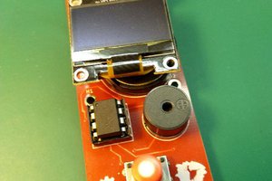
 Thomas Capricelli
 gannon
 8bit-bunny
Hello. Thank you for including me in your project. I will look for some way to help. Thanks