 finallyfunctional
I Built A Prototype!
Below is a video where I built a small section of the treadmill to test what it would be like.
If I can think of solutions to the issues I described I may make a new version.
A Concept for a Cheaper Active Omni-Directional Treadmill
Many Omni-directional treadmills exist today and I see most if not all of them falling into one of two categories.
- Passive - omni-directional treadmills that rely on a smooth, low-friction surface that the user slides his feet on. Also commonly known as slidemills. Examples of these are Omni One by Virtuix and the Kat Walk C.
- Active - omni-directional treadmills that use motors to actively move the platform the user is on. Examples of these are the Infinadeck, ACTVR, OmniDeck, and Strider VR.
Each category has its own set of advantages and disadvantages. Slidemills have less moving parts so are cheaper and easier to maintain, but some users may find that sliding instead of actually walking feels uncomfortable. Active treadmills can actually move the floor below you so that it feels very close to actual walking. But active treadmills tend to be more expensive, with the Infinadeck going for $40,000 to $60,000 each for example, have more moving parts so is more likely to break down, and can suffer from inertia problems.
Here I will explain my own concept for an active omni-directional treadmill. My concept should be cheaper or as cheap to make as other active omni-directional treadmills, not suffer from inertia problems, is scalable to any size, and easy enough to build that anyone with a 3D printer, saw, drill, and basic tools could build one for himself.
When I first started thinking about my own active omni-directional treadmill concept, my first priority was to try to make it as cheap as possible. You could make an omni-directional treadmill out of omni-wheels using a design similar to the Celluveyor.
But omni-wheels are not exactly a cheap option when you consider that you would need many of them to make a treadmill out of. I also considered if ball-transfer units could be used, but they are noisy, can't be motorized, and aren't cheap enough either.
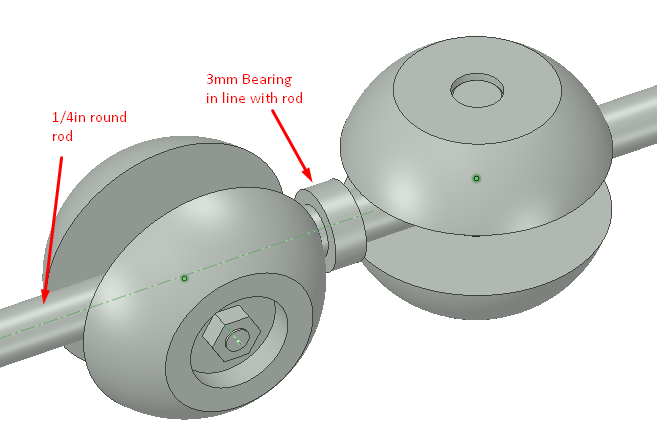
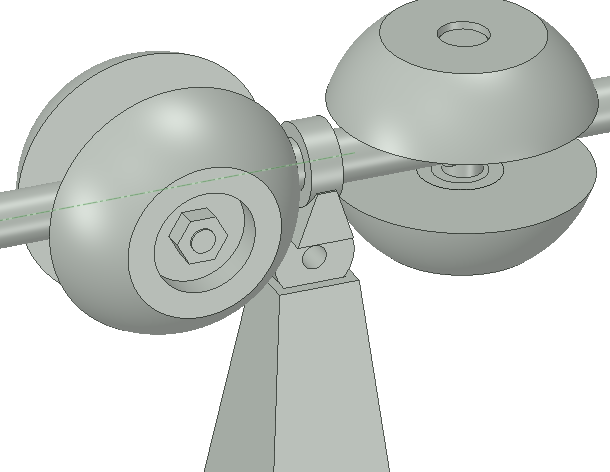
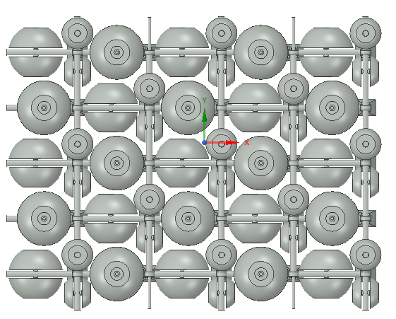
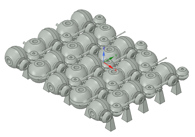
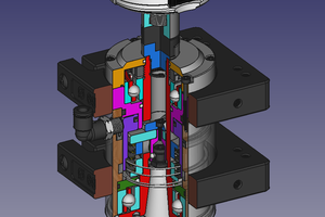
So my first idea was to use simple rollers instead of omni-wheels or ball transfers. A simple roller would be very cheap to make and it wouldn't be too expensive if you needed hundreds of them. The next challenge came with deciding how the rollers should be arranged to achieve have omni-directional capabilities. A the rollers going one way would just produce the motion a regular treadmill produces, so you'd need half of the rollers rotated 90 degrees so you could also have sideways motion. But, each roller has an axle going through it. If you have a set of rollers for forward/back and another set for sideways, won't the axles collide? This stumped me for a while, but then I thought of a solution. Yes, if the rollers are all the same diameter they will, but they don't have to be the same diameter. That led me to make this quick 3D-model.
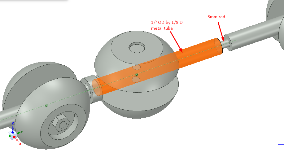
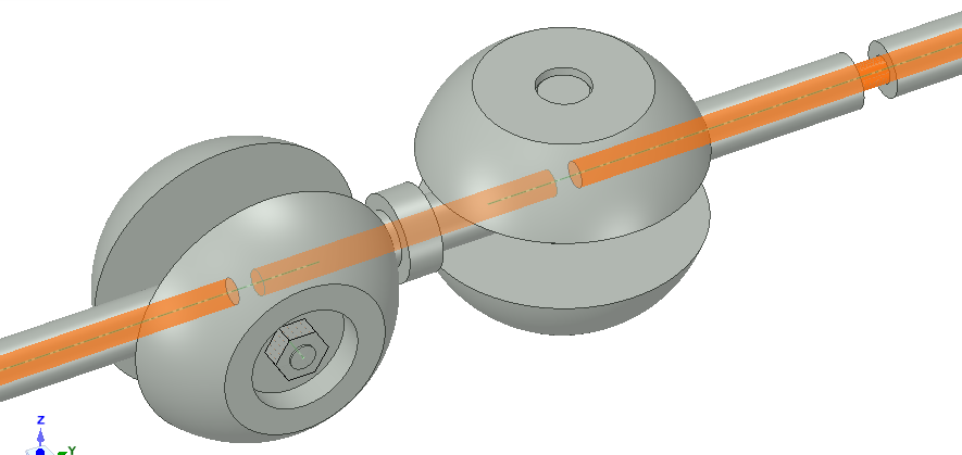
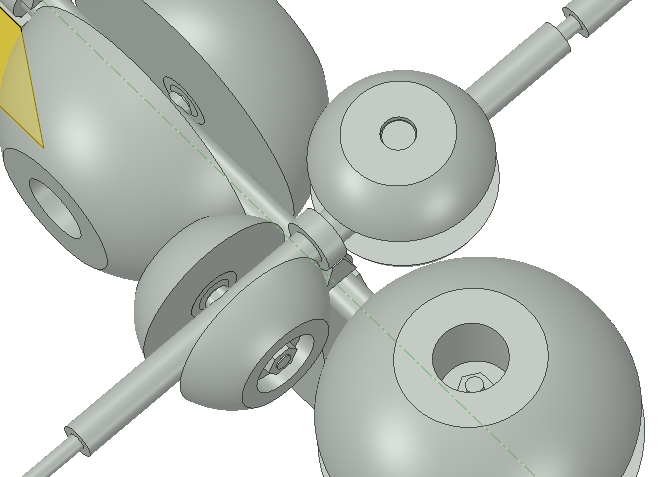
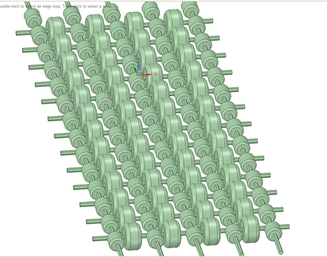 This treadmill consists of two sets of rollers. The rollers are of different diameters, so the axles do not intersect as you can see more clearly here.
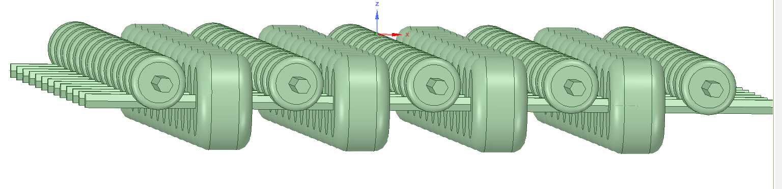 Of course, the obvious problem with this idea is that it will produce a lot of friction. If you're walking forward, the sideways rollers will just create sliding friction. This could possibly be reduced by having groves on the rollers or adding a low friction material on the rollers, but then you're going to have to try to balance low-friction with also having enough traction for the rollers to actually move you.
After this I was again stumped for a while. I decided that the roller had to be a little more complicated, but still be cheap to produce. I recalled the omni-sphere design that I developed for a previous version of my VR shoes.
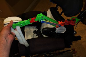
These were partially omni-directional, meaning they could produce powered forward, backward, left, and right motion, but nothing in-between. There are other omni-sphere designs, such as this Omni-Crawler....
 Mike Turvey
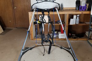
 Jan
Jan