 Evan
EvanApple sold millions of iPads the year they were introduced. These devices were capable of browsing the web, watching movies, and playing games, with up to 10 hours of battery life and an intuitive touchscreen display. Apple essentially defined what a tablet should look like, and competitors are still playing catch-up.
However, all the original iPads are many years out of date. While some apps still work, and some can be made to work by jailbreaking the device, due to a lack of software support by Apple, these tablets are unable to do many of the things they used to be capable of.
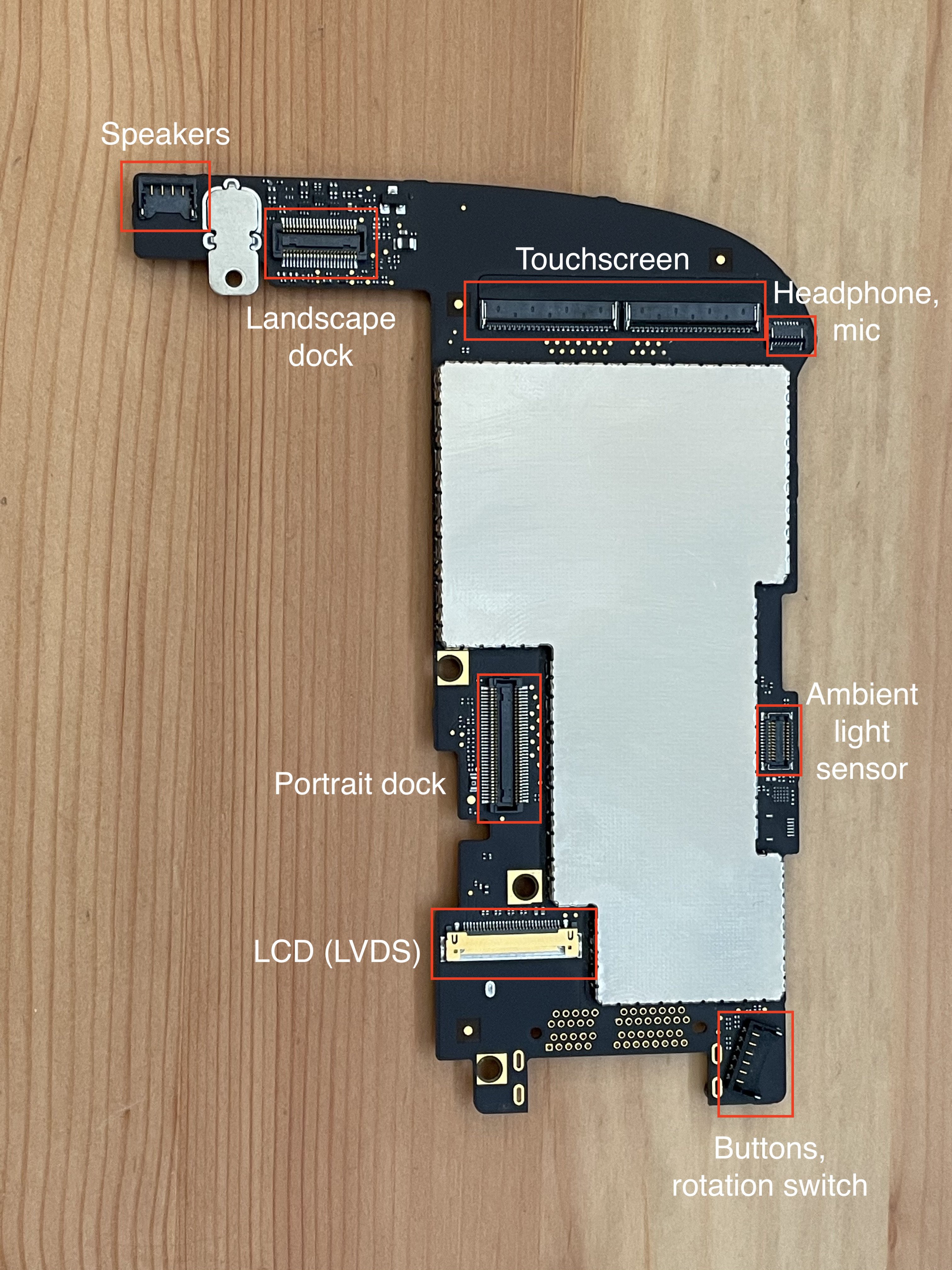
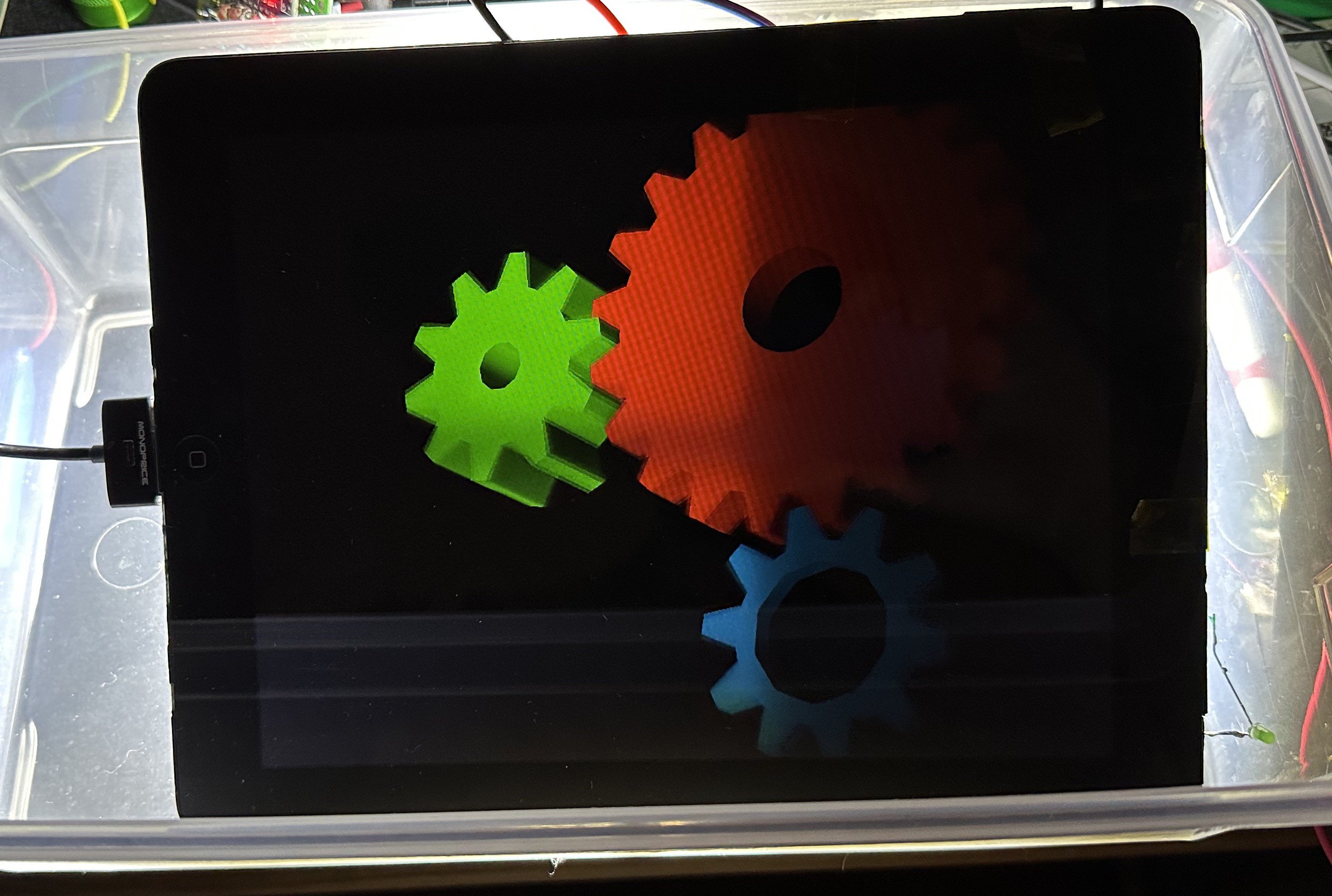
The hardware isn't terrible, though! The iPad has a nice touchscreen, an okay LCD, a beefy battery, and enough buttons and ports to make it still useful as a computing device.
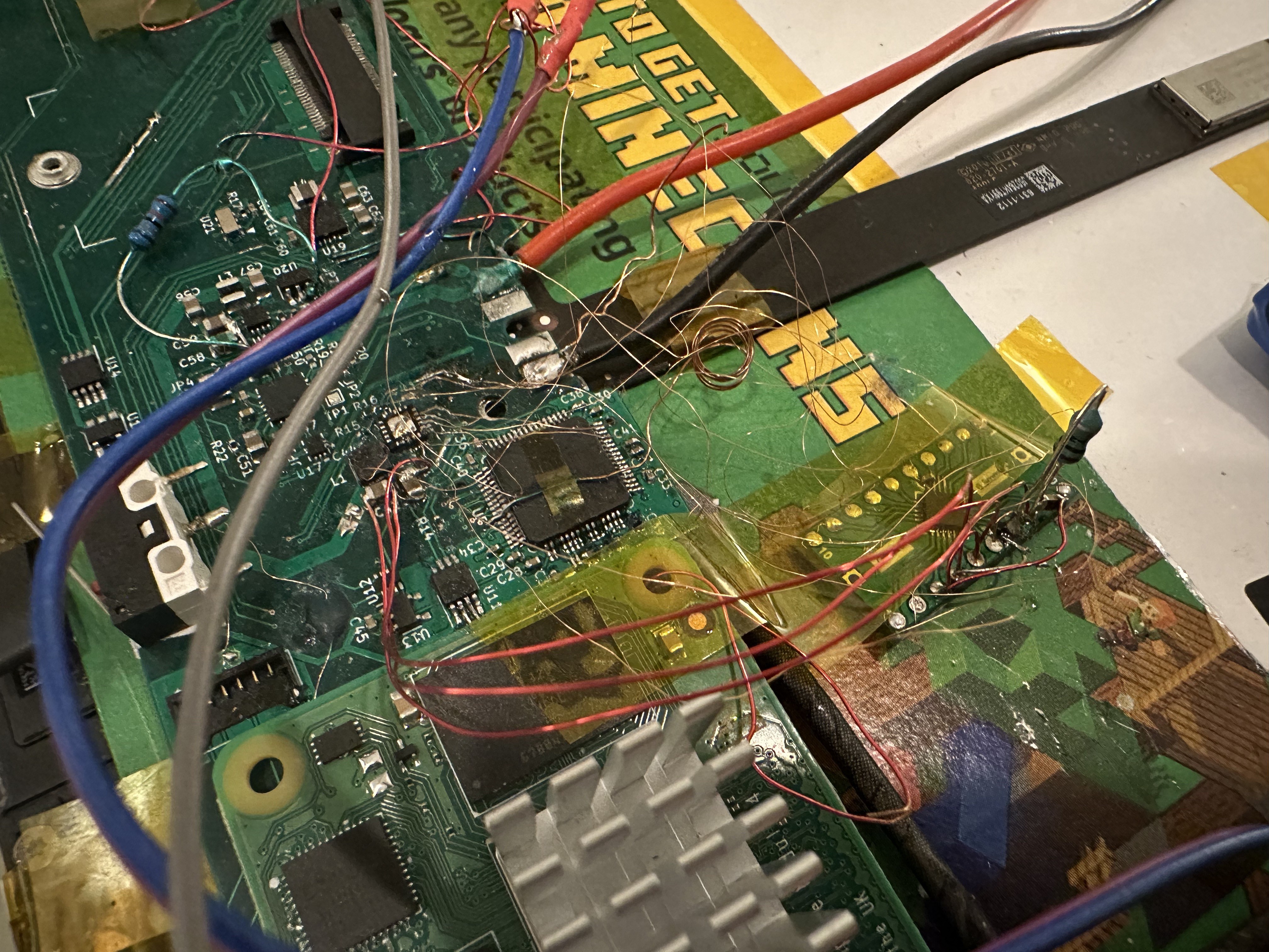
With this project, I intend to make a logic board for the original iPad based around the Raspberry Pi CM4 or another similar SoM. This will allow people to upcycle their obsolete iPads into fully-functioning tablets, which should be able to run Linux and Android.
Hopefully by giving these venerable devices a new lease on life, we can keep some of them out of landfills.


 kevinjkrieger
 Tirdad sadri nejad
 bobgreenwade
Really nice your frequent updates currently.