 Evan
EvanThe biggest unknown to me when starting this project was how I was going to interface with the touchscreen. In general, all the other connectors on the logic board are some sort of standard signaling scheme, like analog audio, I2C, USB, SDIO, or LVDS. I've never worked with a capacitive touchscreen before, so I had no clue where to start. (I've never worked with LVDS before either, but I at least have an idea where I'd learn things about it.)
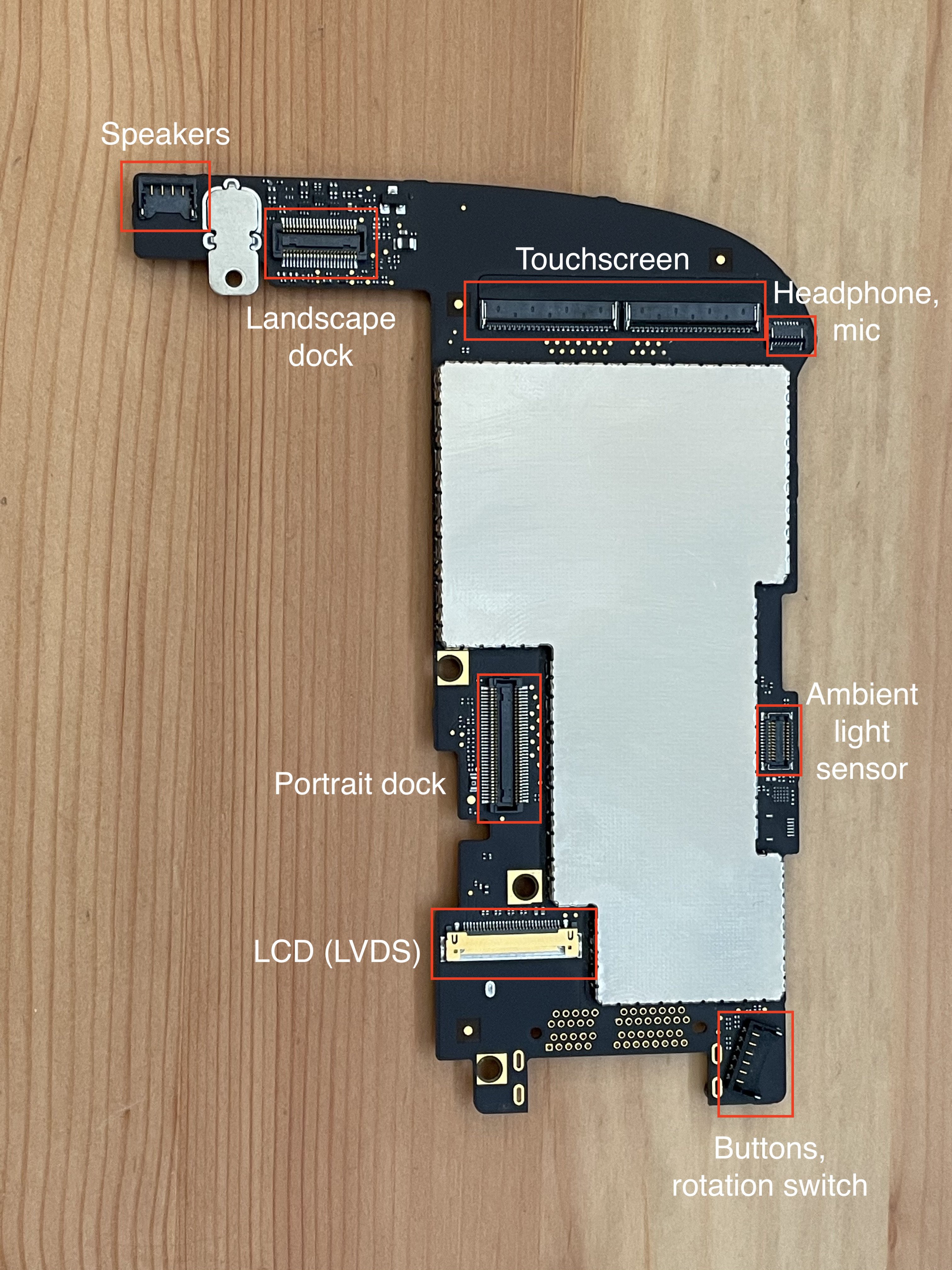
A lot of my initial research began with the iFixit teardown for the iPad. In addition to information on how to get into the device, they've got all the part numbers for the various chips. They identify the TI CD3240A1 as the touchscreen controller, but my internet searches find nothing helpful about this. Other articles identify the BCM5973 as part of the touchscreen system. I can find distributors willing to sell me the BCM5973, but no datasheets or anything.
Taking a different approach, I looked at what touchscreen controllers are available to buy on Digi-Key, etc. The easiest to buy controller family I found is the Microchip (Atmel) MaxTouch family, such as the MXT1664T3. (There are also some Cypress chips available on Mouser, but the publicly available datasheets for these are really just spec sheets, and lack any useful information on how to use the chips.)
I also stumbled upon this blog post series over at Mike's Mods about trying to reverse-engineer the iPad 3 touchscreen digitizer. Not exactly the same product (for some reason the iPad 1's touchscreen has 102 pins.), but this does a pretty good job of explaining the way capacitive touchscreens work.
Between the maxTouch datasheet and the blog post series linked above, I gained an understanding of how touchscreens work:
There is a set of parallel wires going across the screen, and another set of parallel wires perpendicular to the first set. One set of wires are "transmit" lines, the other are "receive" lines. The controller will drive one transmit line at a time with some sort of AC signal, while measuring how much of this signal is capacitively coupled into each receive line. When a finger is near the intersection of a particular transmit line and a particular receive line, the capacitive coupling between those two lines will be different (less?) than if there is no finger present.
Mike mentioned that he was able to find leaked schematics for the iPad 3, so I googled around for "iPad A1219 schematics" and was able to find a few sketchy-looking sites that have them. (I won't link them here since it's probably a copyright violation to share them.)
From the schematic, we can learn the pinout of the touchscreen. Like the iPad 3, the iPad 1 has a 30x40 grid, with 40 transmit and 30 receive lines. Unlike the iPad 3, though, each receive line is brought back to two separate pins on the FFC connectors. (Except for MT_PANEL_IN<29>, which only ends up in one place for some reason.) 3 ground pins, 40 transmit pins, and 2x30-1 receive pins adds up to 102 pins, split across two 51-pin connectors.
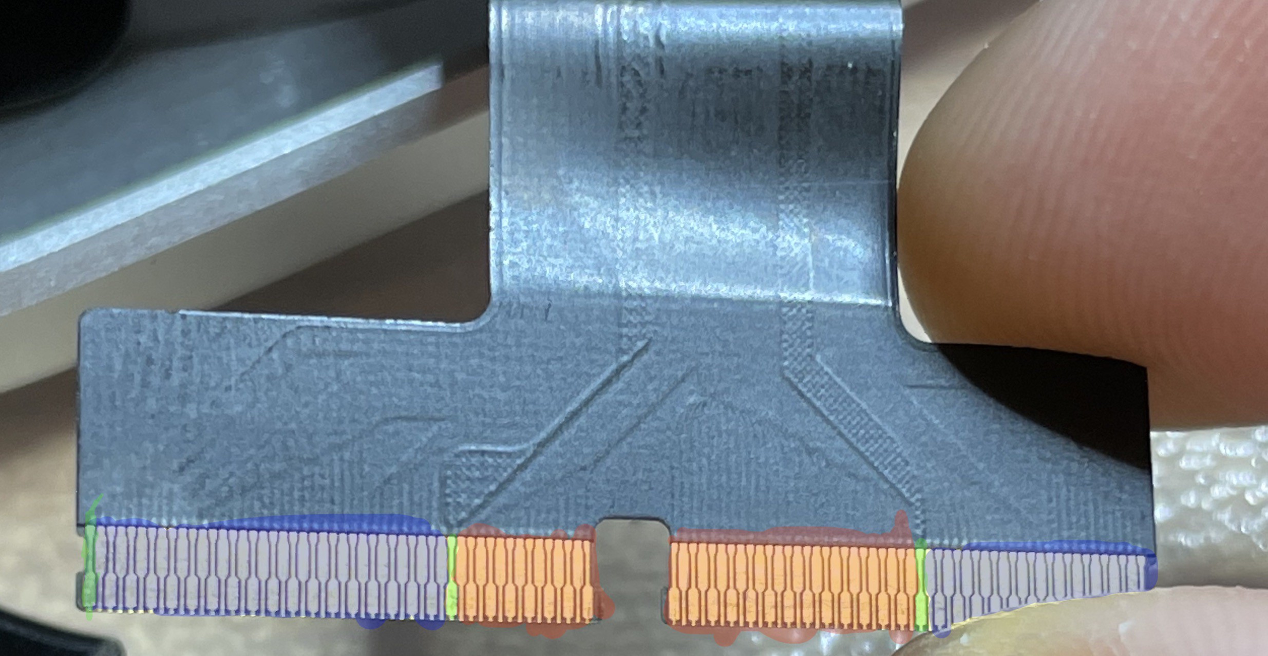
Here I've highlighted the receive pins in blue, the transmit pins in red, and the ground pins in green.
In theory, all I need to do is build a board with something like the MXT2952TD wired out to two FFC connectors that will fit this flex cable. The iPad uses Molex 502250-8451 connectors, which are no longer sold, but the 502250-5191 is still available from Arrow and seems compatible.
I started laying out such a board, but then learned that it's expensive (hundreds of dollars) to get boards made with 3 mil tracks / 3 mil space and the 0.15mm minimum drill holes required to fit in between the pads on the mXT2952's 0.5mm-pitch BGA footprint.
I then switched to the automotive version of the controller, the MXT2912TD-A. This is a 0.5mm-pitch LQFP with 176 pins, which is much easier to lay out. (With the downside that it's massive -- 24mm x 24mm, instead of 5x10mm for the 2952.) Then I noticed that the automotive parts aren't available in quantities lower than 40 (at $15/unit, so $600 per lot.) Back to the 2952, and I guess I'll just have to suck it up and spend $300 on PCB manufacturing and hope I don't mess it up.
Ideally, I'd get one board made that does everything, but in order to keep the expensive part small (and avoid having to pay lots of money if I make a mistake in a different part of the circuit), I think I'm going to make a small board with just the touchscreen controller, and put everything else on a different board.
I've put my KiCad files up at https://github.com/EvanKrall/ipad_touchscreen_driver. If you have any feedback, please let me know! I'm still quite new at PCB design.
Discussions
Become a Hackaday.io Member
Create an account to leave a comment. Already have an account? Log In.