 Evan
EvanChip shortage problems
Shortly after my last project log, I tried to place an order for all the new components that I'd need for the next revision of my board, as well as re-stocking anything that I had already used most of. I discovered that my backlight controller of choice had gone out of stock with indefinite lead times, so I had to swap to a different backlight driver. (I switched from the TPS61176 to the TPS61177, which was the next cheapest suitable controller on DigiKey.)
I ordered my parts then modified my PCB design to accommodate the new chip.
Fit Testing
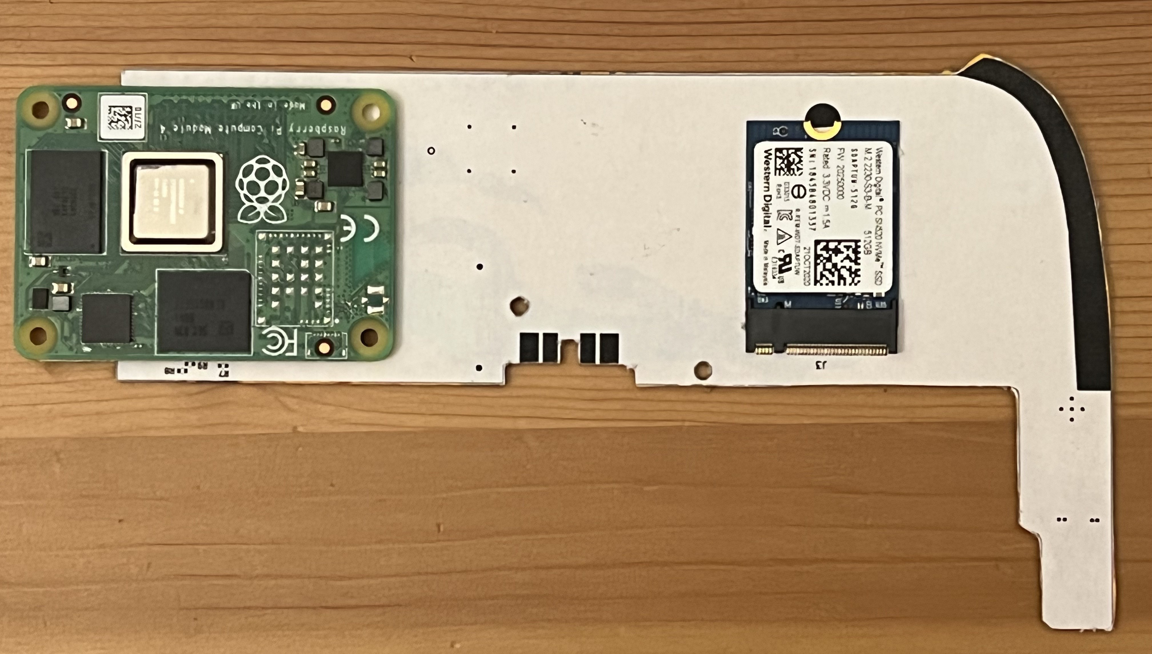
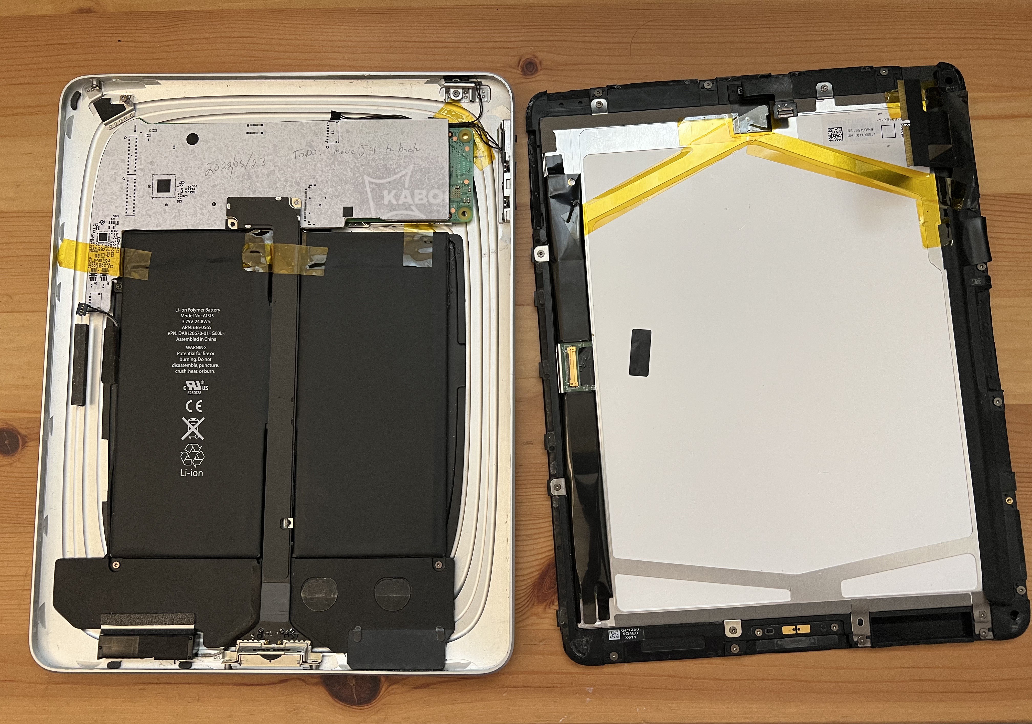
Once I had parts in hand, I made a mockup of my board by printing the front and back solder mask layers on separate sheets of paper, and then gluing them to either side of a piece of cardboard taken from a soda can box. (This stackup comes remarkably close to the 0.8mm thickness of my PCB.) With some double-sided tape, I affixed the connectors for the largest components -- the CM4 and the NVMe SSD -- snapped the CM4 and SSD in place, and did a fit test in my iPad case. The screen did not want to drop into place.
I found a few things that I could change to improve the fit:
- I rotated the CM4 180 degrees, so that the BCM2711 processor (the thickest part of the CM4) is closer to the center of the case (where the iPad is thicker, so there's more room)
- I moved almost all of the other components from the front to the back of the board, in between the SSD and the CM4, leaving only the connectors (dock, ambient light sensor, touchscreen, buttons) and the touchscreen controller and audio codec. (The touchscreen and audio bits are on the other end of the board, and I didn't seem to have any trouble fitting that end.) This meant the battery charger, 3.3v buck-boost (for the SSD), 5V boost (for the CM4), the DSI-LVDS converter, and the backlight driver all moved to the back.
I also needed to adjust the edge of the board to leave a spot where the LVDS cable can come up from the back of the case to the front of the board.
All these changes required re-routing a significant chunk of the board, which took me a few weeks.
Touchscreen controller testing
Meanwhile, I decided to test the GT9113/GT9110 touchscreen controller on the previous iteration of my board. I had messed up the orientation of the FFC connectors for the touchscreen on that revision, but I figured I should at least test whether I can get the Linux kernel to talk to it. I'm glad I did -- I discovered a few things that were wrong with my PCB.
First of all, the Linux kernel driver wants the INT pin from the controller to be wired to a GPIO pin. I hadn't connected that pin anywhere, and didn't leave myself any extra space on the pad to solder a wire to. I tried several things to bodge a connection to this wire before finding something that worked:
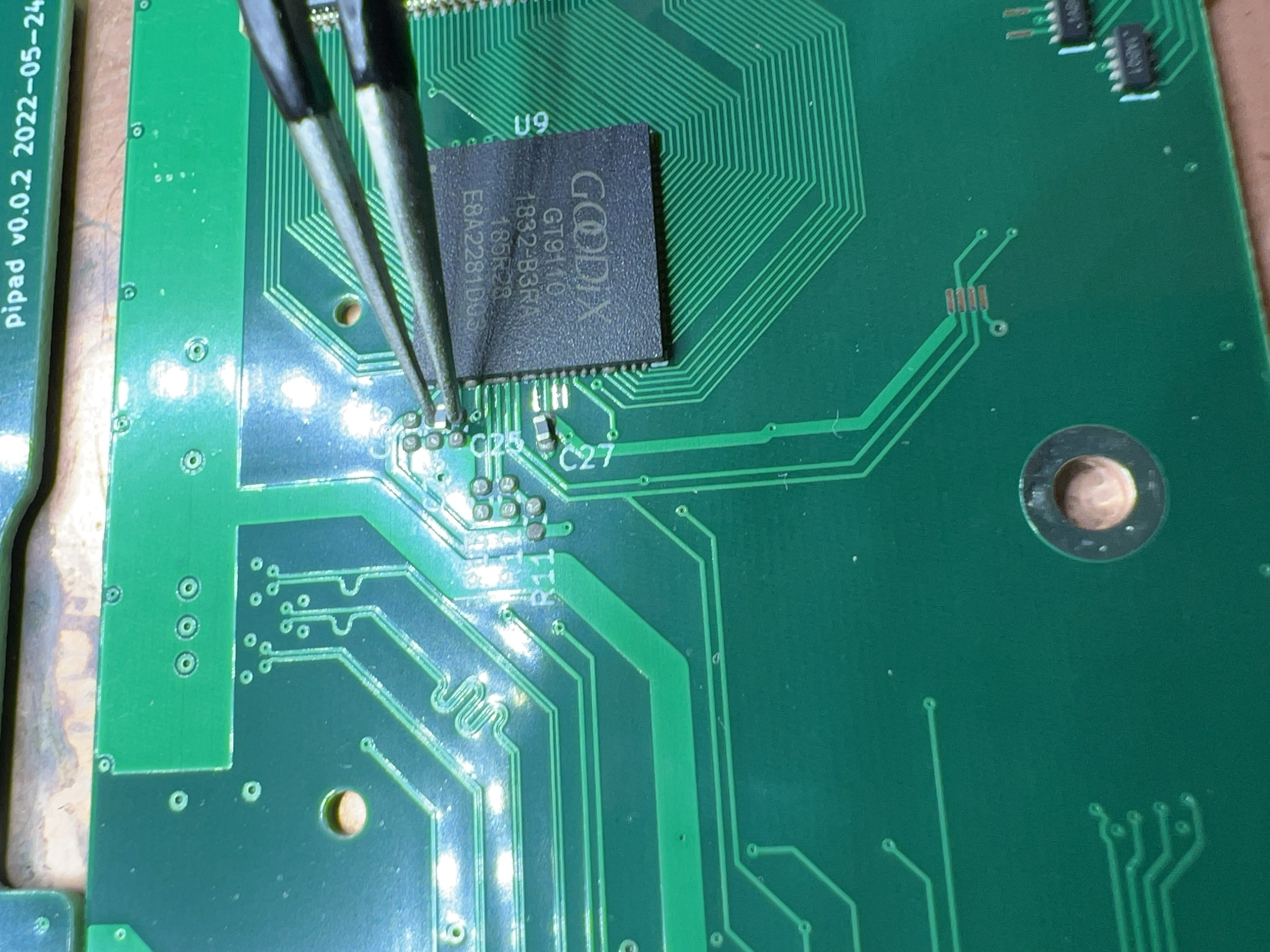
- poking an enameled wire at the edge of the chip and trying to get it to solder in place: the pins on the chip are visible on the side, but even my finest soldering iron tip is enormous compared to the 0.4mm between adjacent pins.
- removing the IC, soldering a 40AWG wire to the pad, and soldering the IC back down. It turns out, even 40ga wire is thick enough to keep the rest of the pads from reliably making contact when soldering. I still feel like I could've gotten this to work by adding more solder, but it was just too finicky, so I got frustrated and tried another approach:
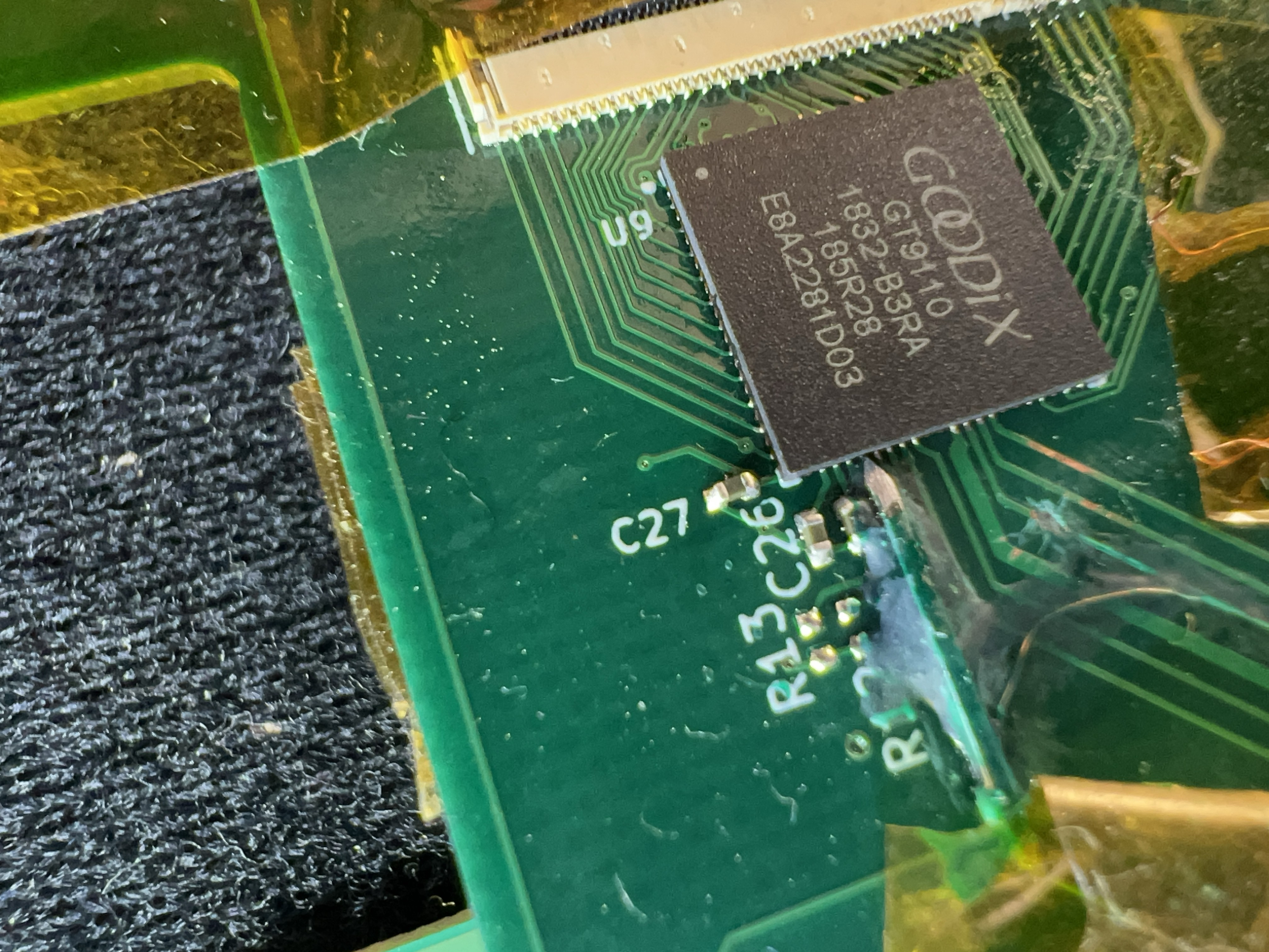
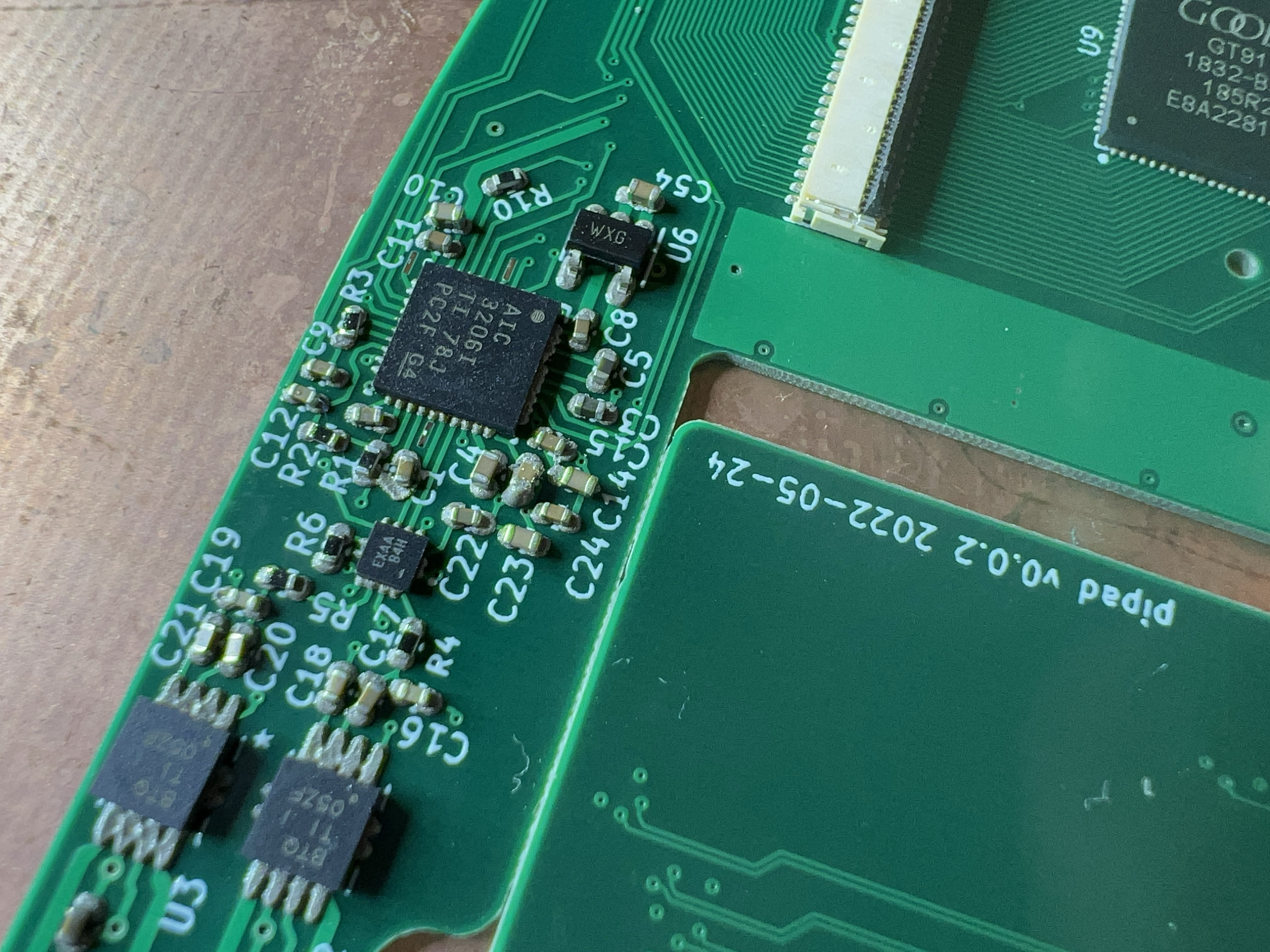
- (what ultimately ended up working, mostly?) I took a standard 0.1" header pin, and used a file on 3 sides to sharpen it to a point that's flush with the 4th side. I then glued this in place with some UV-cure solder mask, which is my new favorite thing for bodges. Assuming you use a thin layer, it cures in like 10 seconds under the provided UV flashlight. This is what's shown in the photo above.
Another thing that I discovered was that I couldn't get the GT9113 to be discoverable on i2c at all. (The GT9113 has nearly identical pinout to the GT9110, but is meant to be used with a GTM802 companion chip, which I think is basically just a microcontroller.) I figured these chips would be basically identical, but maybe they're more different than their pinouts suggest.
After swapping the 9113 for the 9110, I was able to talk to it over i2c. However, I had a strange problem: the GT9110 wouldn't respond on the I2C bus for the first few requests made by the Linux driver. After that, it would respond fine. I'm not really sure what was happening. Maybe my GT9110 is bad? Maybe my bodged connection is marginal, so I've effectively made an RC circuit on the INT pin?
In any case, I'm pretty sure I'd be able to work around it with driver-level hacks, so I incorporated these changes into my PCB design:
- INT pin wired to a CM4 GPIO pin.
- Drop the traces for the GT9113's ARM_RST and Wake pins, since I'm committing to the GT9110.
Fit testing again
When I finally finished all of those routing changes, I made a new mockup using the same cardboard+printer paper technique as before. This almost fit, but not without some pressure holding the screen down (and flexing it slightly 😬). I discovered that the back of the screen was pressing against the button connector, and that I could make everything fit cleanly by moving that connector to the back.
With J4 on the back, it seems like everything would fit cleanly - the screen closed nicely, without requiring any pressure.
I rerouted the traces for the button connector (and moved some other traces from the back to the front to make room), added a bajillion tiny test points (0.25mm x 1mm) to the board - essentially replacing every NC flag in my schematic with a test point.
Ordering, assembly, and another fit check
At some point, I finally felt confident ordering my PCBs. (I also threw in boards for a quick side-side project). They arrived about a week ago, and I soldered together my prototype over the course of two nights:
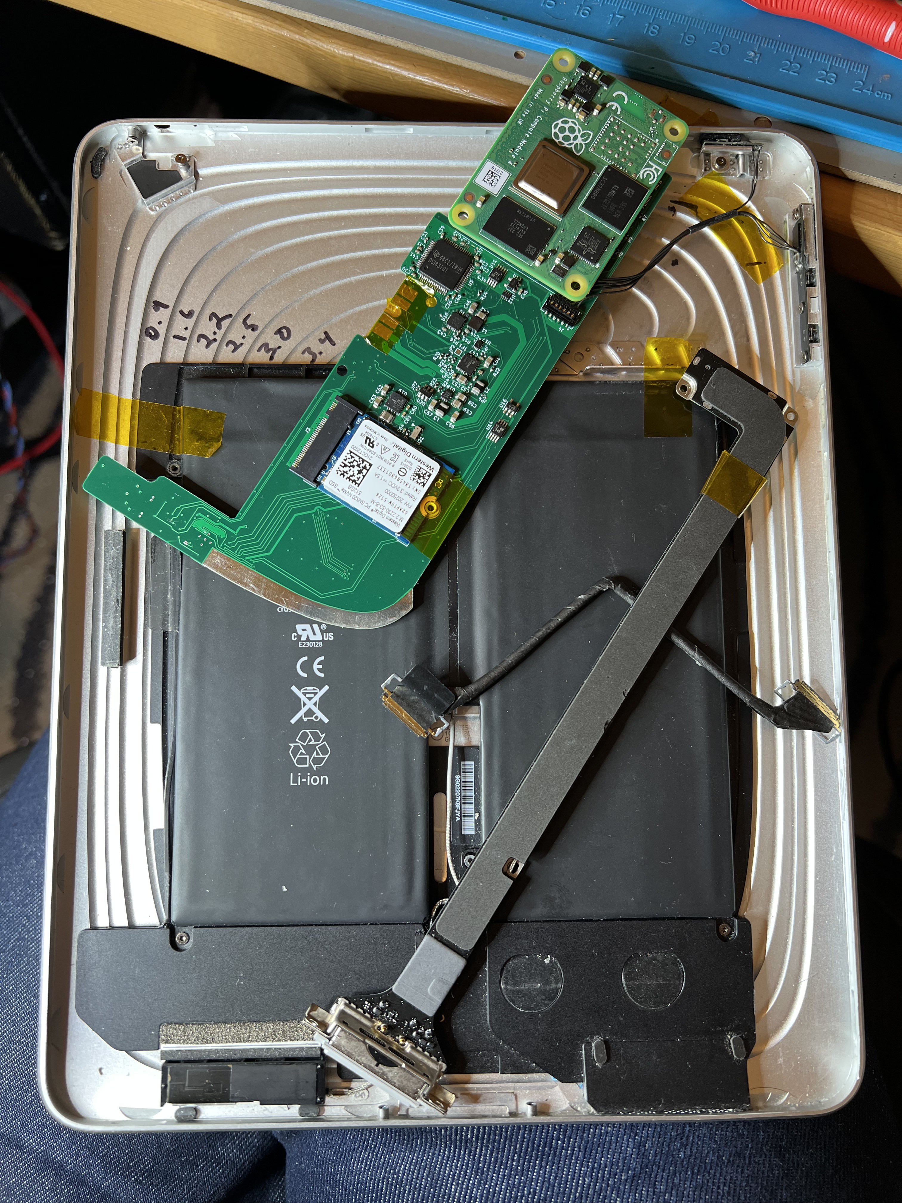
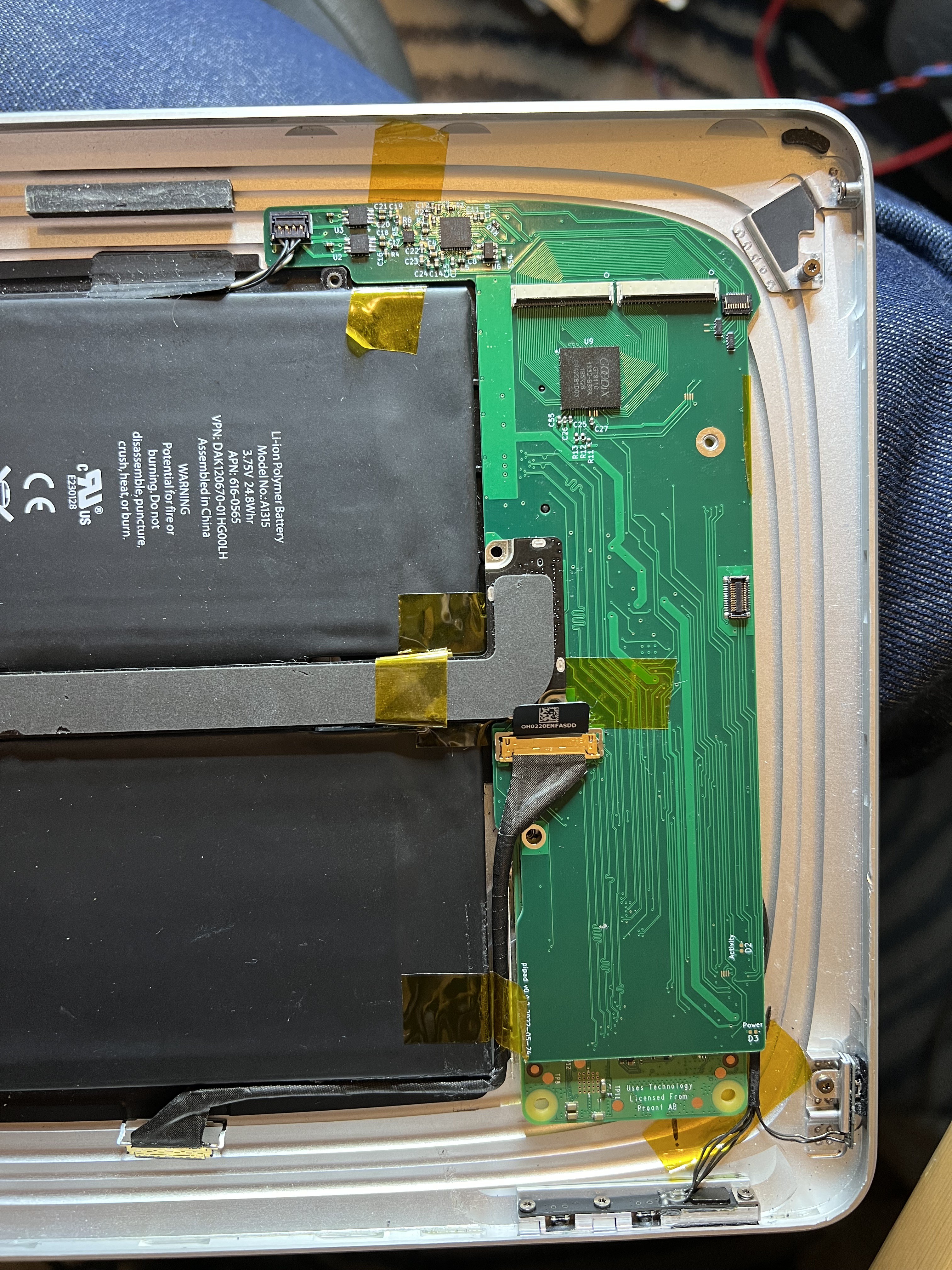
This almost fits. I think I didn't cut enough of the edge where the LVDS cable comes up -- that corner sticking out near the mounting hole is getting in the way a bit. Fortunately, there are no traces in that area, so I should be able to remove some material with a file.
Testing the new board
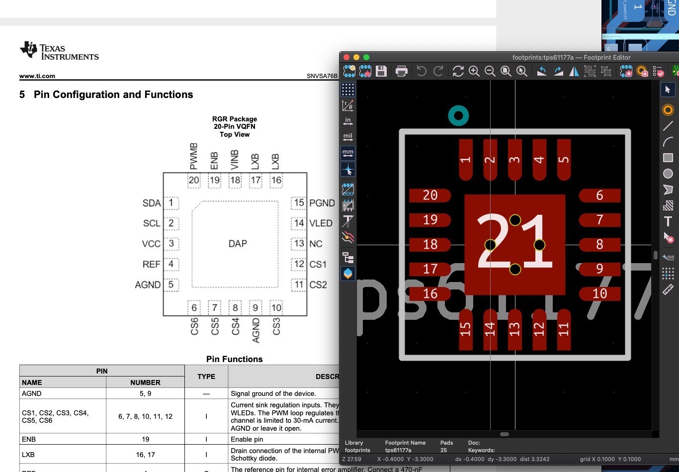
Essentially, I mirrored the footprint for the TPS61177. I have attempted to fix this by flipping the chip upside-down and painstakingly bodging wires to nearby components and traces:
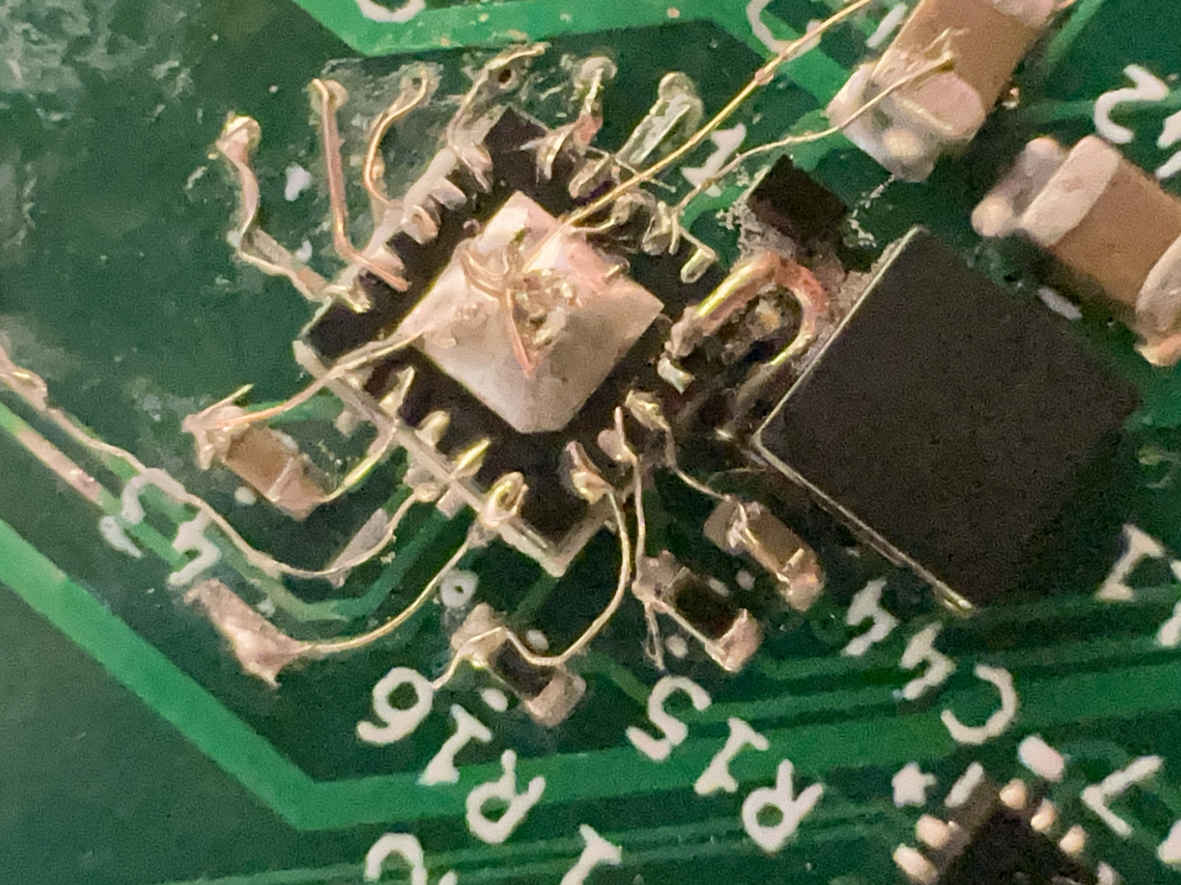
(I also replaced the inductor and IC with fresh components.) When applying power, this no longer tries to draw 9 amps. Will it actually work? I won't be able to test this until I can get something (preferably the CM4) configuring it over i2c and giving it PWM input.
Can this actually run the CM4?
After verifying that I have what seems to be a stable 5V rail, and nothing else trying to catch fire, I enabled serial console on my CM4 while it was still on the CM4IO, tested that it worked with a USB-TTL adapter I had lying around, then anxiously moved the CM4 over to my board.
Applying power, I get nothing on the serial port. 5V and 3.3V rails seem stable...
I soldered an LED and resistor between 3.3V and the activity LED pads (I need to adjust my schematic for the activity LED -- I had just put the LED between the activity pin and ground, but it's an active-low, open collector pin.).
The activity LED flashes a few times -- when looking at the voltage on it with my logic analyzer, it seems like there's actually a ton of activity at first; but still, no output on the serial port.
I moved the CM4 back to the CM4IO to verify that serial output was still working there, and at one point I used my multimeter to probe the GPIO pins to verify that I had the GPIO pins in the correct orientation. While probing the 5V pin, my probe slipped, and shorted 5V to 3.3V! The CM4 is now dead 😢.
I have ordered a new CM4 from Welectron, a German distributor, since that was the only place that had any CM4s in stock according to rpilocator. One silly slip of a multimeter probe has cost me 64 EUR and a week or two of waiting for the replacement to arrive.
(The internet suggests I might have just damaged the PMIC on the CM4, and that I might be able to repair it by replacing the MXL7704 chip, so I'll be ordering some of those from AliExpress soon, but those will likely take longer than the replacement CM4 to arrive. EDIT: this source claims theMXL7704-P4 on the CM4 is different than the -R4, and isn't compatible: https://forums.raspberrypi.com/viewtopic.php?t=322613)
Discussions
Become a Hackaday.io Member
Create an account to leave a comment. Already have an account? Log In.
Where were you able to buy a Goodix chip or any other touch controller chip at all? I try to make some experiment with a controller chip and a digitizer, but cannot find any to buy as a chip standalone.
Are you sure? yes | no