I've been testing out the GT9110 for the past few days, and finally got it working today.
My board uses a Goodix GT9110 touchscreen controller, which is closely related to a few other parts (GT911, GT928, etc.), and is basically the only touchscreen controller that I could find which met my requirements:
- Has enough drive and sense pins to work with my touchscreen
- A reasonable footprint which doesn't require expensive, high-density PCBs (which excludes the mXT2952, an 0.5mm-pitch BGA)
- Available in small quantities for a reasonable price (which excludes the MXT2912TD-A)
- Actual datasheets are available (which excludes a bunch of Cypress chips)
- Linux drivers are available
(I should note that I haven't found an English datasheet for the GT9110, only one in Chinese. However, I did find English datasheets for related chips, like the GT911 and GT9113. These, plus Google Translate, were enough to lay out my PCB.)
On my previous iteration of the board, the i2c communication to the GT9110 was unreliable -- it wouldn't respond on i2c until a little while after the INT pin went high, which made the Linux goodix driver unhappy. I had guessed that might've been because the bodge I had to do for the INT pin wasn't making a good connection.
Initial progress
I dug up the device tree overlay file I had written for testing, and updated the GPIO numbers to match my new board revision.
Fortunately, the new board doesn't have the same communications issues from the old board -- the Linux driver was able to talk to the GT9110 successfully, and create a file under /dev/input/event*.
Getting stuck
However, beyond initializing the driver, nothing else would happen. The INT pin would go high during driver initialization, and wouldn't change when I touched the screen. No further i2c communication was happening. Looking at the drive pins with an oscilloscope, I could see nothing was happening.
An error immediately stood out to me:
[ 67.112771] Goodix-TS 1-005d: Direct firmware load for goodix_9110_cfg.bin failed with error -2
I searched the web for a goodix_9110_cfg.bin, but couldn't find any example files. I did, however, find a few relevant threads:
- https://forums.raspberrypi.com/viewtopic.php?t=267434
- https://forum.khadas.com/t/connect-goodix-touchscreen-to-vim3/13955
- https://forums.raspberrypi.com/viewtopic.php?t=240001
Nobody seems to mention needing a goodix_9110_cfg.bin (or goodix_911_cfg.bin, goodix_928_cfg.bin, or whatever); everybody managed to get their touchscreens working after a while by fixing basic issues with their device tree overlay files.
Thinking I might have the wrong settings for my interrupt pin, I tried various combinations of pull-up/down/hi-Z, interrupt configuration (IRQ_TYPE_EDGE_FALLING, IRQ_TYPE_EDGE_RISING, IRQ_TYPE_LEVEL_HIGH, IRQ_TYPE_LEVEL_LOW). None of these seemed to help - several of those combinations prevented i2c communications entirely.
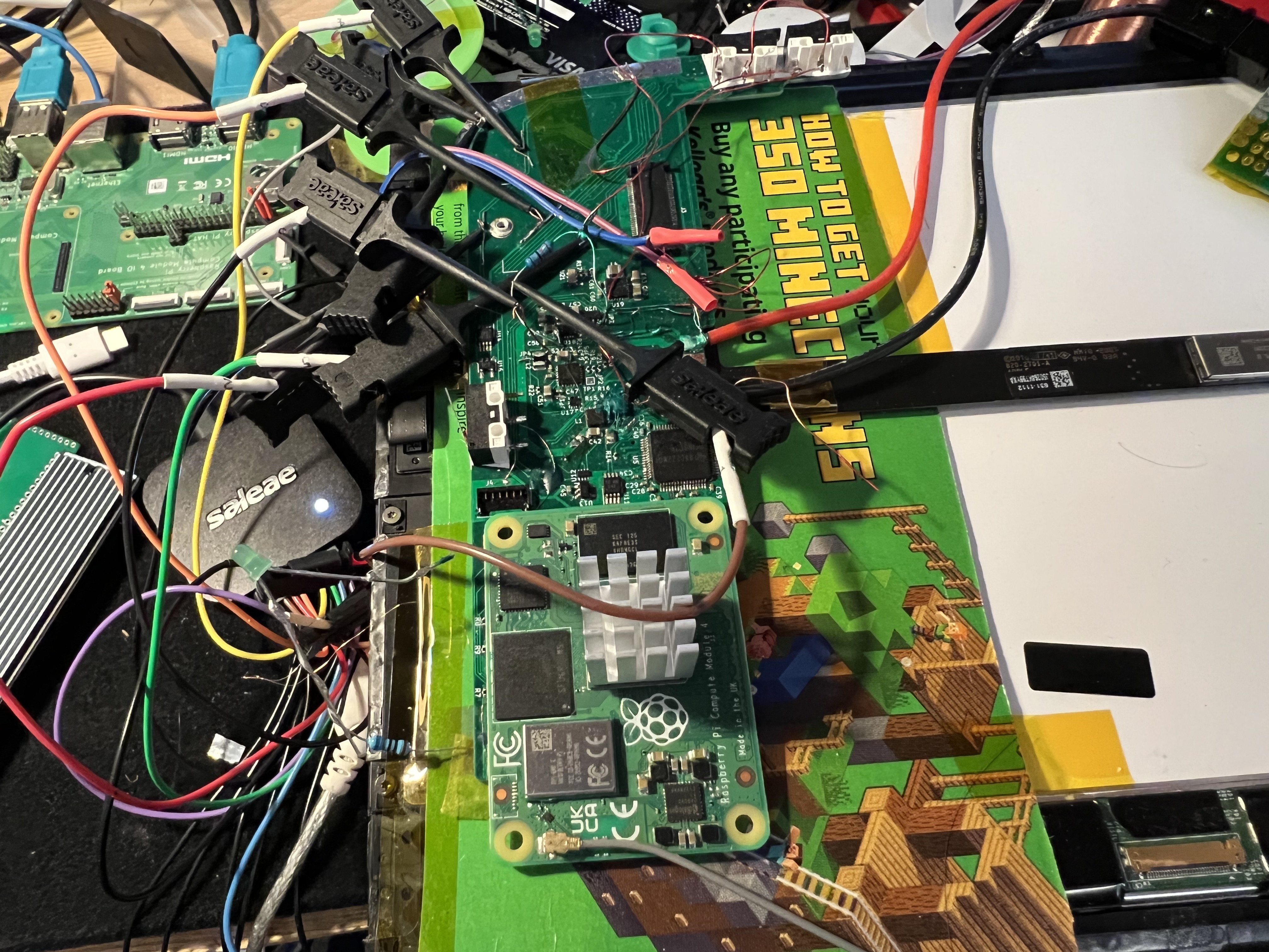
Eventually, I gave up on that and focused on the firmware load error again. Adding a bunch of debug printfs to the driver and watching i2c communication with my logic analyzer (I'm using the Logic 8 from Saleae), I could see that it was:
- Identifying the GT9110 on i2c
- Trying to load the firmware from disk, and complaining that it isn't there. (The internet tells me it's looking in /lib/firmware, among other places)
- Reading a bunch of data from the GT9110 starting at register 0x8047, which is the beginning of the configuration registers.
- Leaving the INT pin high, never signalling that it had data.
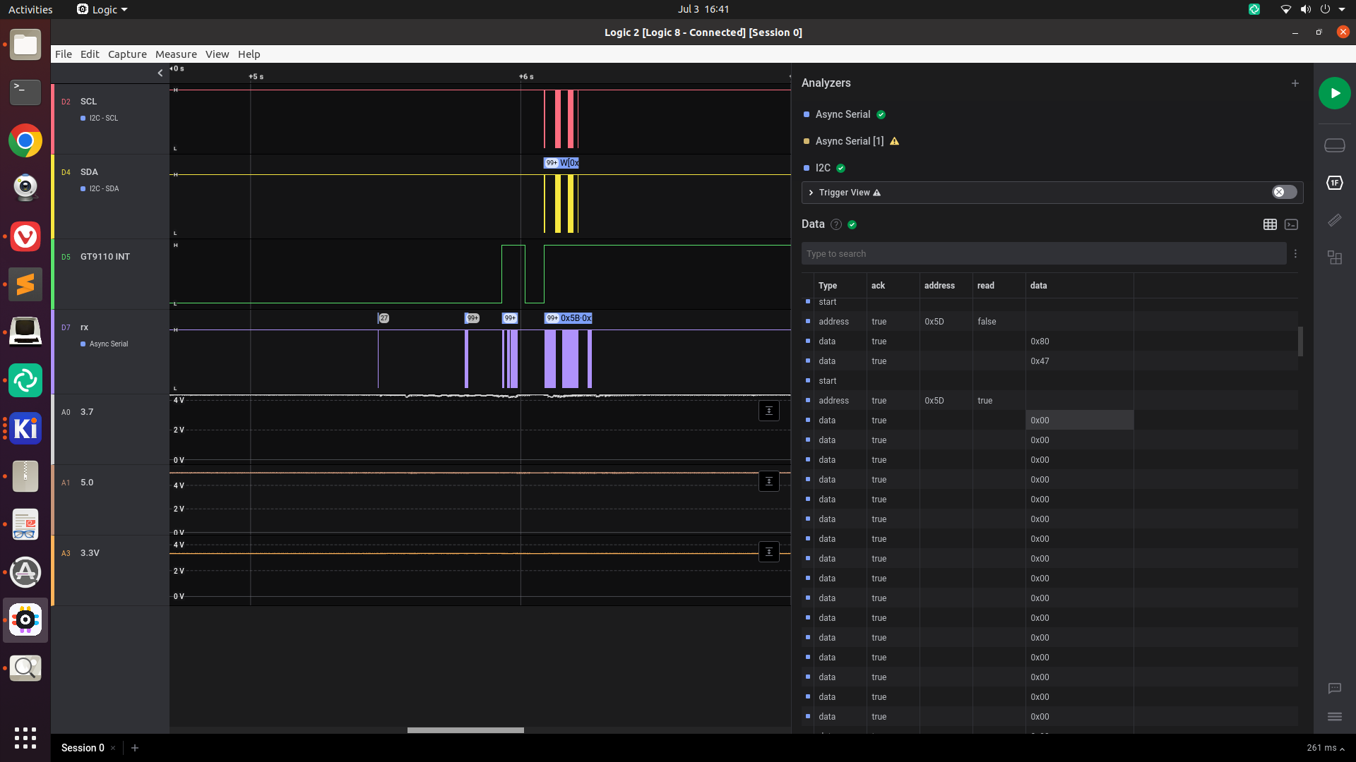
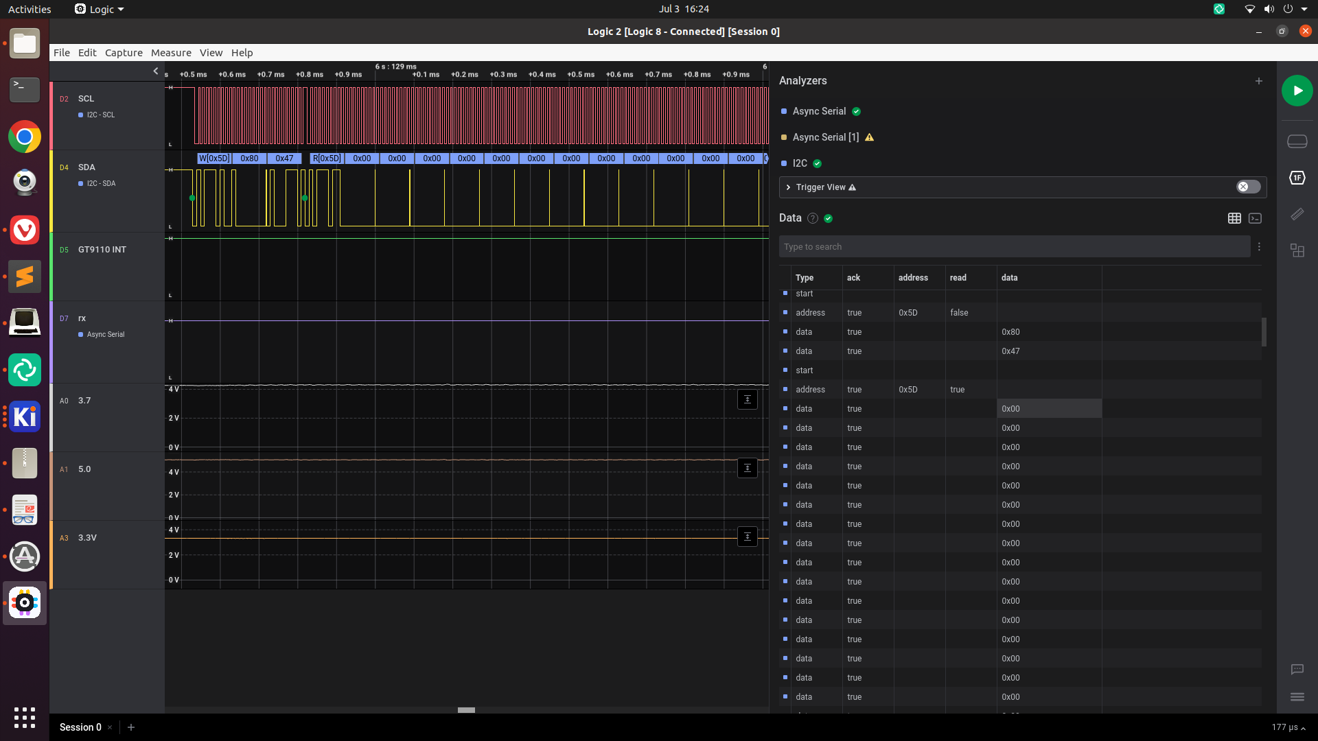
If I'm understanding this correctly, this means all of the configuration registers were set to 0. Unlike a lot of other chips, it seems like the GT9110 has no default values. I probably want to set those to nonzero values.
From my reading of the driver source code, the only way to change the configuration is through a firmware file, so I guess I really need to find or write one.
Breakthrough
I eventually stumbled on this Stack Overflow question, which pointed me to this Arduino library for interfacing with gt9x controllers, where they've defined a constant called g911xFW which is 186 bytes long. This length happens to match the GOODIX_CONFIG_911_LENGTH constant defined in the Linux driver code.
(The Stack Overflow question also had a link to the GT911 Programming Guide, which is handy.)
I wrote these bytes to a file, copied it over to my CM4 and put it in /lib/firmware/goodix_9110_cfg.bin, and tried loading my driver again. This time, the i2c and interrupt lines were extremely active:
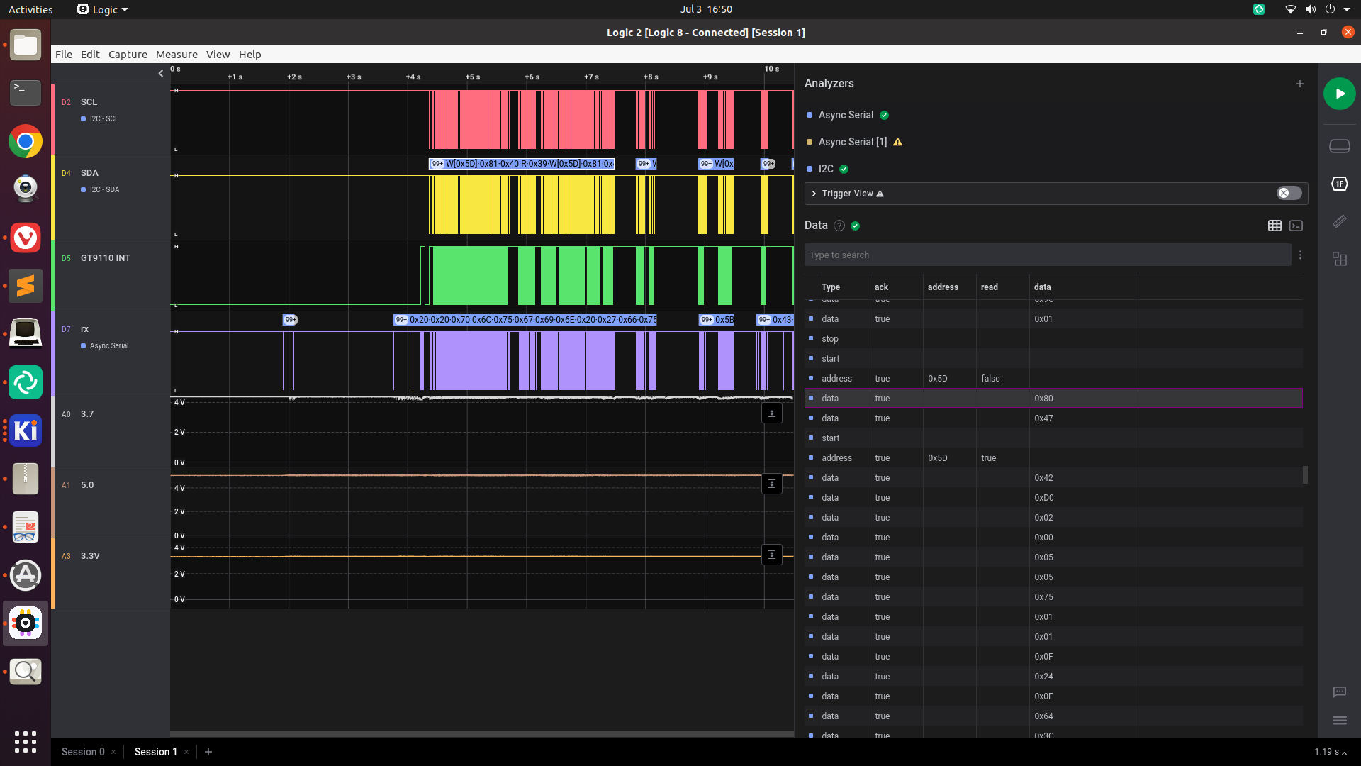
Zooming in, we can tell that immediately after the INT pin goes low, the driver is requesting several registers, starting with 0x814E.
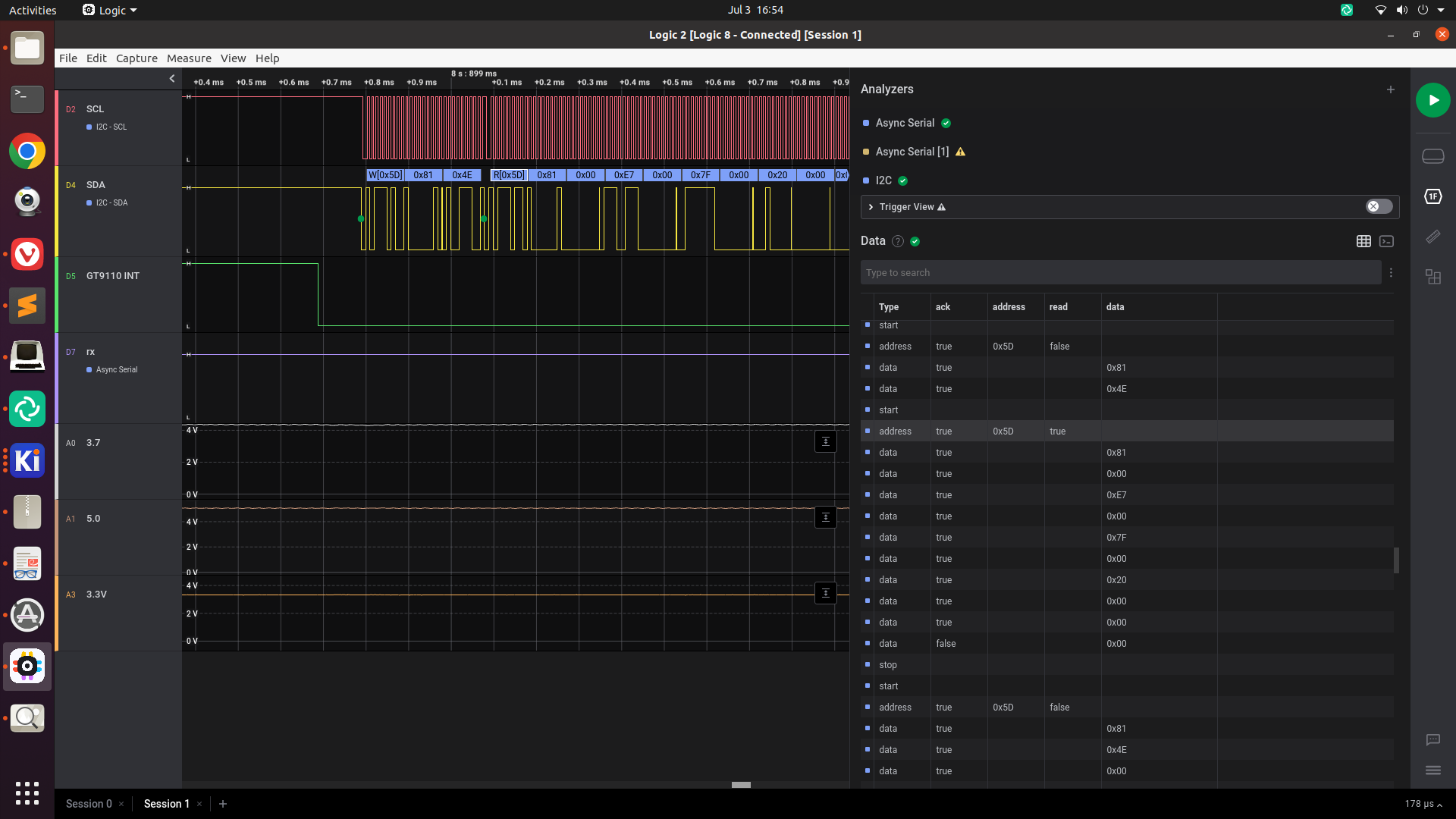
This includes registers 0x8150 through 0x8153, which are the X and Y coordinates of touch 1. This is good! Let's find out if the data is meaningful.
Visualizing the touch data
I wrote a little script to visualize the touch data from /dev/input/eventN using ncurses. Running this with the GT9110 using the configuration we just found, we see that we just get garbage data:

I ended up reformatting the configuration data into something a little more human-readable, with comments explaining which register each value belongs to. A few things stood out:
- The X and Y dimensions (registers 0x8048 to 0x804b) were set to 720x1280, whereas I need 768x1024
- The Sensor_CH0...Sensor_CH13 registers (0x80b7 to 0x80c4) were set to 0x02, 0x04, ..., 0x1C. Similarly, the Driver_CH0 through Driver_CH24 channels were all set to various numbers between 0x02 and 0x28. I'm surprised these didn't just start at 0x01 and go up from there.
- The registers between Sensor_CH13 and Driver_CH0 (0x80c5 through 0x80d4) were all set to 0x00, as were the registers after Driver_CH24 and before Config_Chksum (0x80ee through 0x80fe). These are all marked as "Reserved" in the GT911 programming guide, but I'm guessing these would be Sensor_CH14 to Sensor_CH29 and Driver_CH25 to Driver_CH41 in the GT9110. (There are exactly the right number of reserved registers here for that to make sense).
I tried taking a stab at modifying the configuration data:
- bumping the very first register, config version (supposedly the GT9110 will refuse to take new configuration if this is less than the current version register)
- changing the resolution
- Setting Sensor_CH0...Sensor_CH29 to 0x01..0x1E
- Setting Driver_CH0..Driver_CH39 to 0x01..0x28 (I don't need to set Driver_CH40 or CH41, since my board only uses 40 drive pins)
I wrote a script that converts my human-readable format to a .bin file by stripping out comments and serializing just the values. It also calculates the checksum according to the algorithm from the Linux driver.
Trying out my modified configuration resulted in the INT-line-stays-high behavior again:
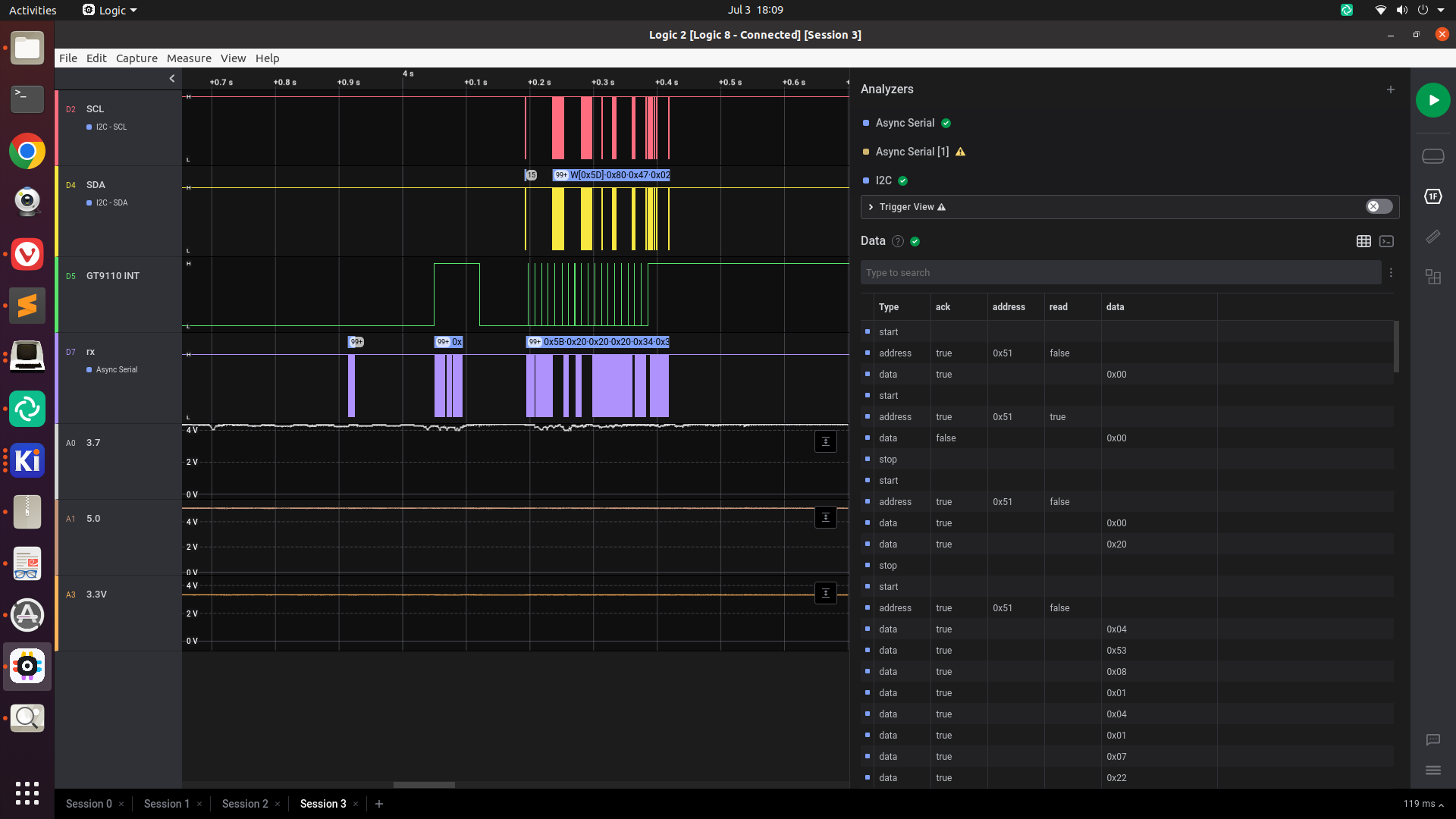
Hmm.
Eventually, I stumbled on this comment from nik-sharky, the author of that Arduino library, who had posted the configuration of their GT9110-based tablet. Trying this out leads to much better results!
I'm not sure exactly what caused the problem, but this configuration starts Sensor_CH0 at 0x00 instead of 0x01. Maybe setting one of these sensor pins to an invalid value causes the GT9110 to crash or something?
I was able to tweak this file with my script, changing resolution and disabling the 2 unneeded driver channels, and things still work.

Conclusion
Getting a GT9110 or other GT9x chip working on a custom PCB seems like it's a lot harder than getting it working on an existing board, since you need to come up with a configuration. An existing board would presumably already be configured, so you just need to hook up i2c and the reset/interrupt pins, and get a working device tree entry. (Once you've configured the chip, it seems like it stores the configuration in non-volatile memory so you don't need to reconfigure it again later. This would explain why nobody else needed to mess with goodix_9110_cfg.bin.)
Having a USB logic analyzer / mixed signal device like the Saleae is super handy for debugging embedded problems like this. While it's possible to watch i2c traffic with Linux debugging tools, it's very nice to be able to visually see the state of the interrupt pin and the i2c communication. Having the ability to copy-paste is super nice, too -- something that would be difficult with a standalone oscilloscope.
 Evan
Evan
Discussions
Become a Hackaday.io Member
Create an account to leave a comment. Already have an account? Log In.
Thank you so much Evan for the firmware. What a work you did ! I was working from time to time on the same issue since 2019 (!) on another board with same feeling about ts initialization, found your post yesterday, and was finally able to make it work last night. Thank you sooo much, huge kudos.
Are you sure? yes | no
This was really helpful in helping me look into a touchscreen problem. Thank you so much for posting!
Are you sure? yes | no
Wow, congratulations on getting the Touchscreen to work. Even the multitouch. Great!
Are you sure? yes | no
Thanks! It feels good to have this working - the touchscreen always seemed like the biggest unknown.
Are you sure? yes | no