 Evan
EvanMy most recent JLCPCB order arrived today, which contained:
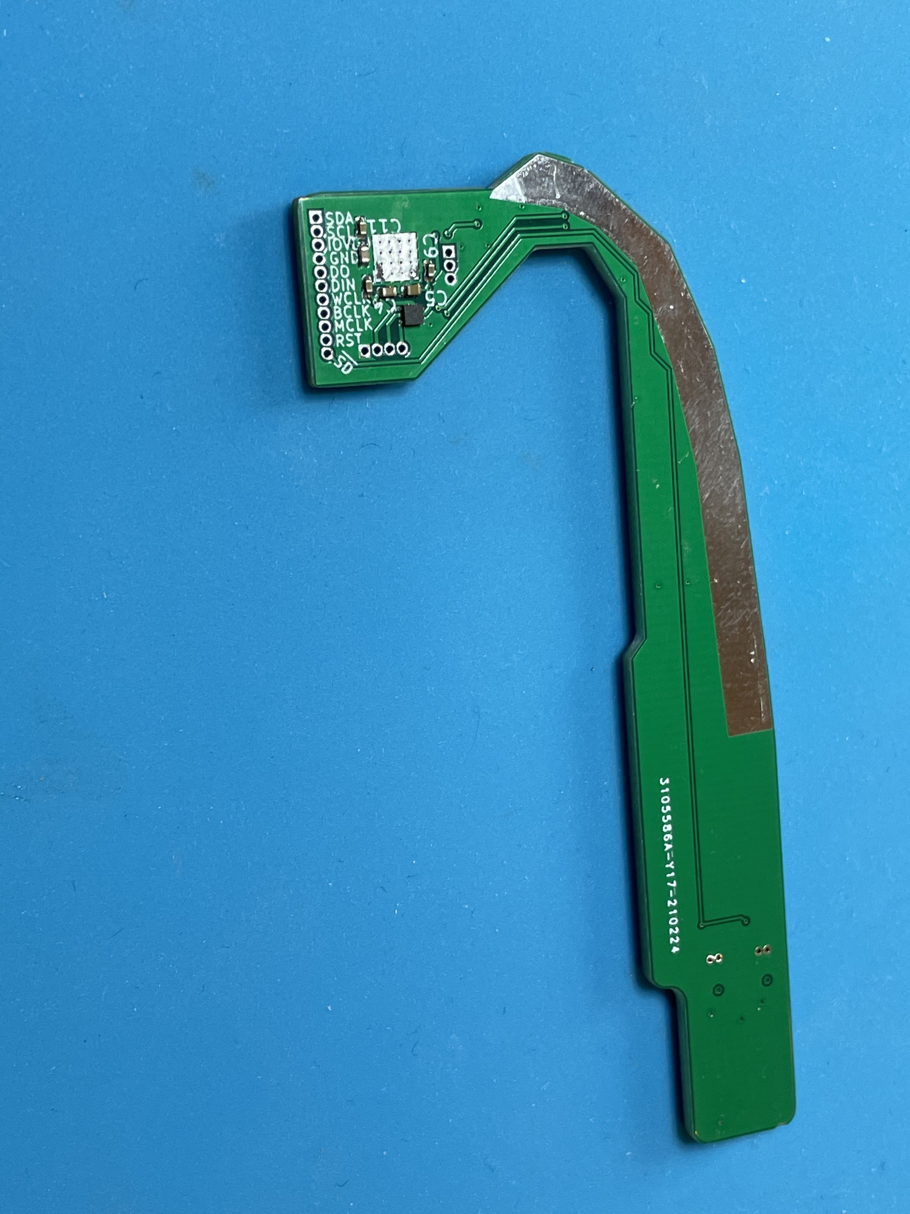
- The i2s soundcard based around the TLV320AIC3104 from TI.
- Breakout board for the AXK770147G used to connect the logic board to the portrait dock connector daughterboard.
- Breakout board for the AA03-S024VA1 used to connect the logic board to the ambient light sensor.
I also included a stencil for the soundcard.
I soldered the breakout board for the AXK770147G with the drag soldering technique, which I definitely need to practice. I needed to do a lot of cleanup with solder wick, plus I seem to have destroyed some of the solder mask. After some basic continuity checking, everything seems okay (though now that I'm looking again, it seems like I may have a bridge between two pins on the bottom right.
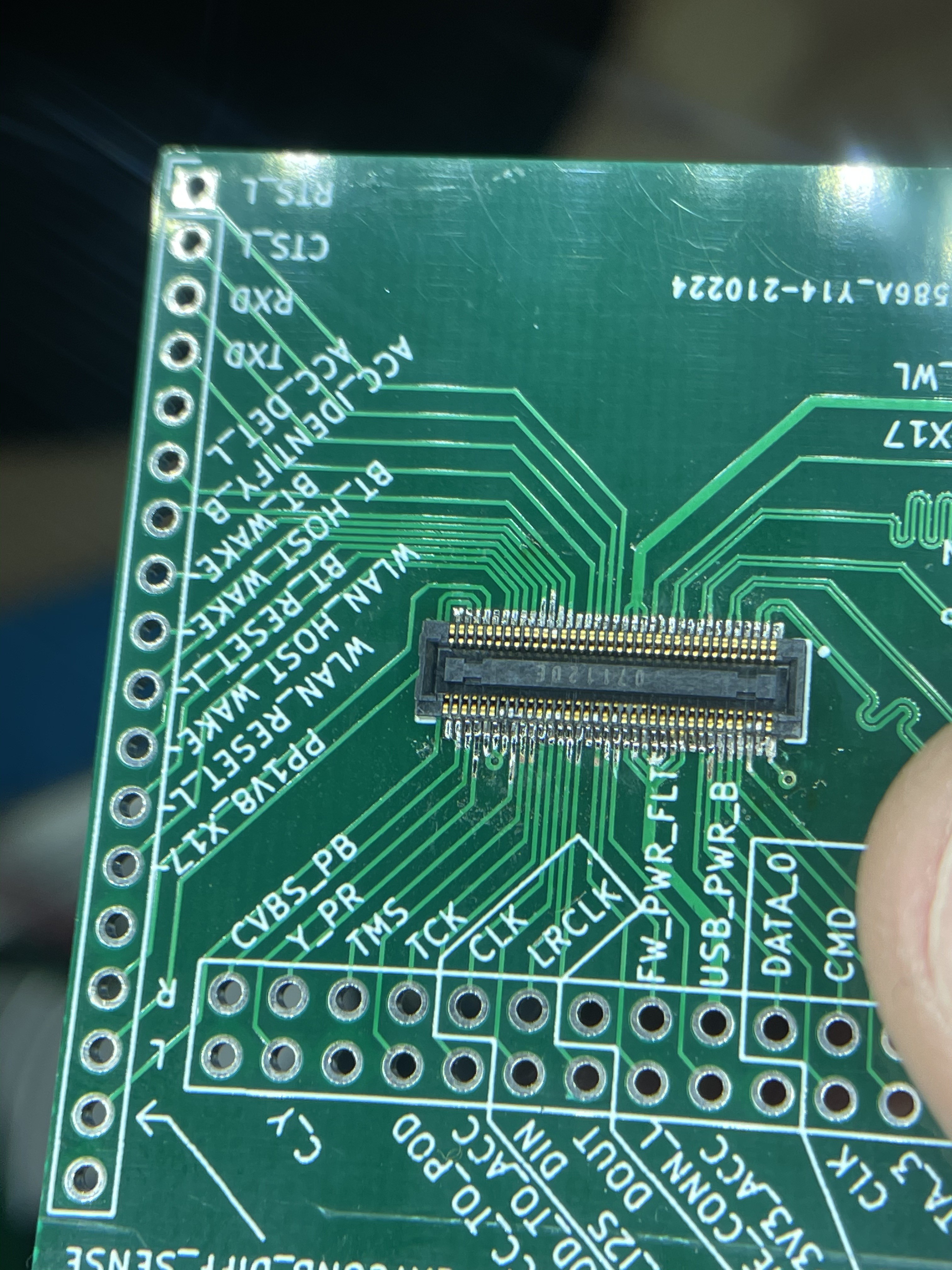
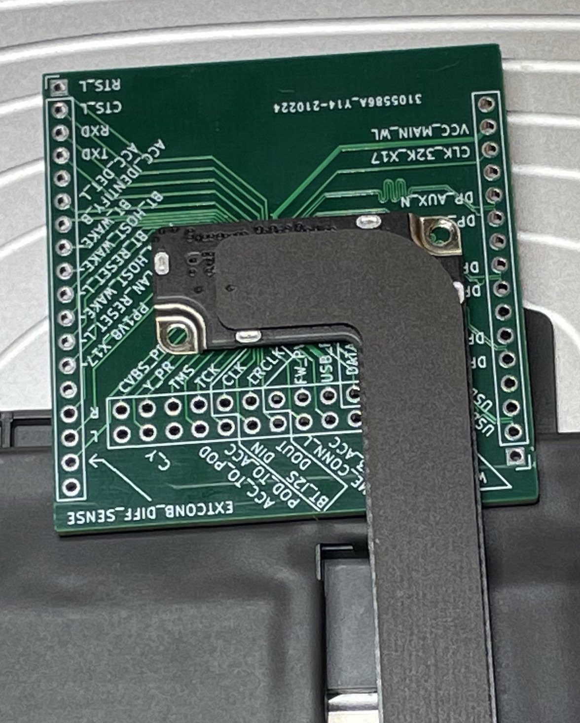
Unfortunately, it seems like I designed it upside-down. (It still pretty much works as a breakout, but I had intended for the double row of header pins to be on the top, not the bottom. Double check the orientation of critical connectors before routing! This isn't a big deal for this board (I mostly ordered this as a way to test continuity to pins on the 30-pin dock connector, and this board still works for that purpose, even if several of the pins are only accessible from the back.)
I also soldered the I2S board. (It's an odd shape because it's supposed to wrap around the touchscreen controller board.)
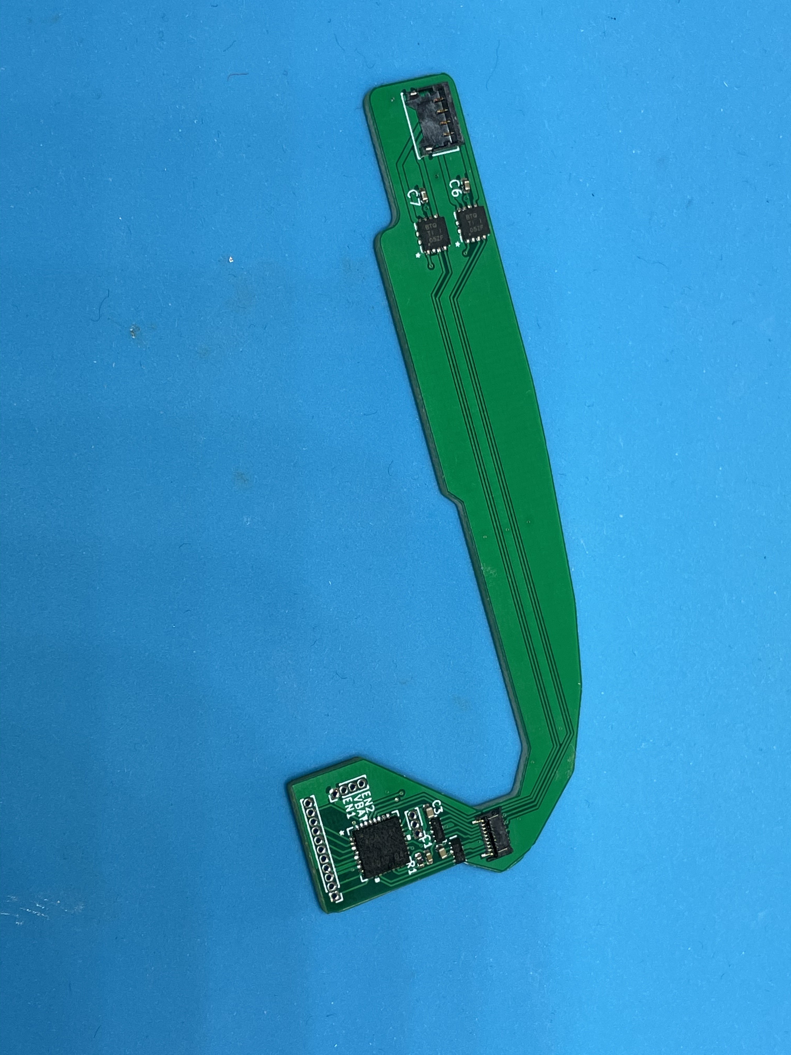
This went pretty smoothly, all things considered! This was my first time working with solder paste, stencils, and hot air. With the stencil ensuring that I had a reasonable amount of paste on each pad, I found the paste very forgiving. Squeegee some paste through the stencil, use tweezers to carefully place each part (nudging as necessary), and then gradually heat with the hot air station. Repeat for the back.
I caught a mistake with this I2S board pretty soon after I submitted the JLCPCB order -- I had laid it out with 0402 footprints for the 220uF capacitors, which you cannot get in such a small footprint. I've updated my board layout for 1206 footprints. I may end up adjusting the board so I can have JLCPCB assemble most of it for me -- put all the passives on one side, so I'm only doing the larger ICs. Before I reorder this board, I want to test it. In the mean time, I ordered the highest-capacity 0402 caps you can get on Digikey (22uF). This will mean I have terrible bass response, but I should still be able to test basic functionality.
(I'm tempted to redo this board with a codec with ground-centered "capless" headphone outputs. These ICs provide their own negative voltage rail with a charge pump, and can drive the headphone output to negative voltages. This avoids the need for bypass capacitors, and provides even better bass.)
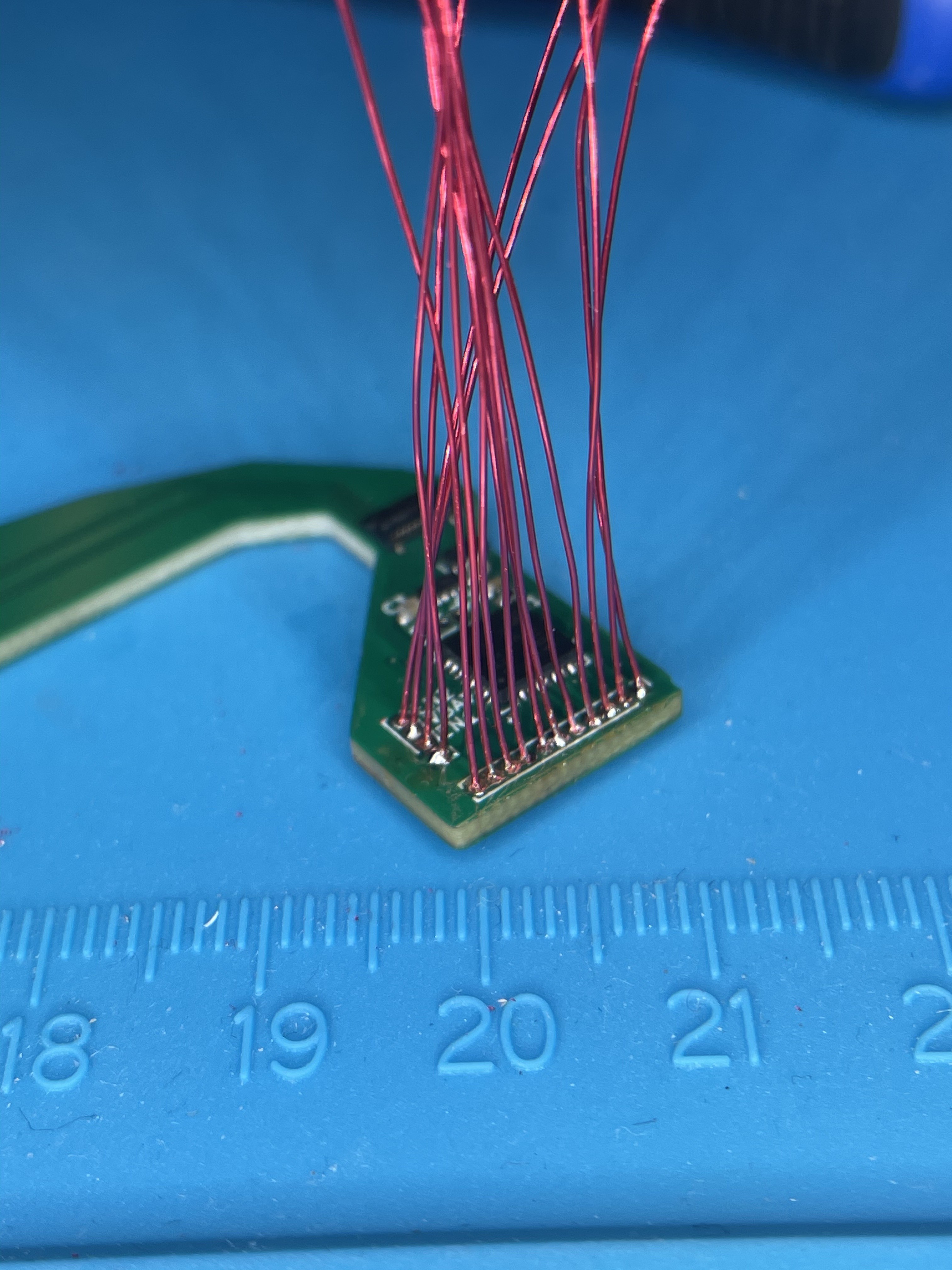
For some reason, I had decided to use 1mm-pitch header holes on this board. I guess I was hoping if I got the board right, I could leave it as is and use small wires to connect to other boards.
Most forms of hookup wire I have on hand have insulation that is larger than 1mm diameter, so I ended up going with enameled magnet wire. Magnet wire takes forever to strip.
I think in the future, for small-pitch headers, I might go for 1.27mm. The standard rainbow "Dupont" jumper wires that you can find for cheap with 0.1" male or female pins on either end seem to be 1.27mm-pitch ribbon cable, so it would be much easier to solder some ribbon cables in place. Either way, if I do header pins this small again, I'll buy actual header pins and get a breakout board to 2.54mm headers manufactured. Maybe I should just buy some generic FFCs and breakout boards?
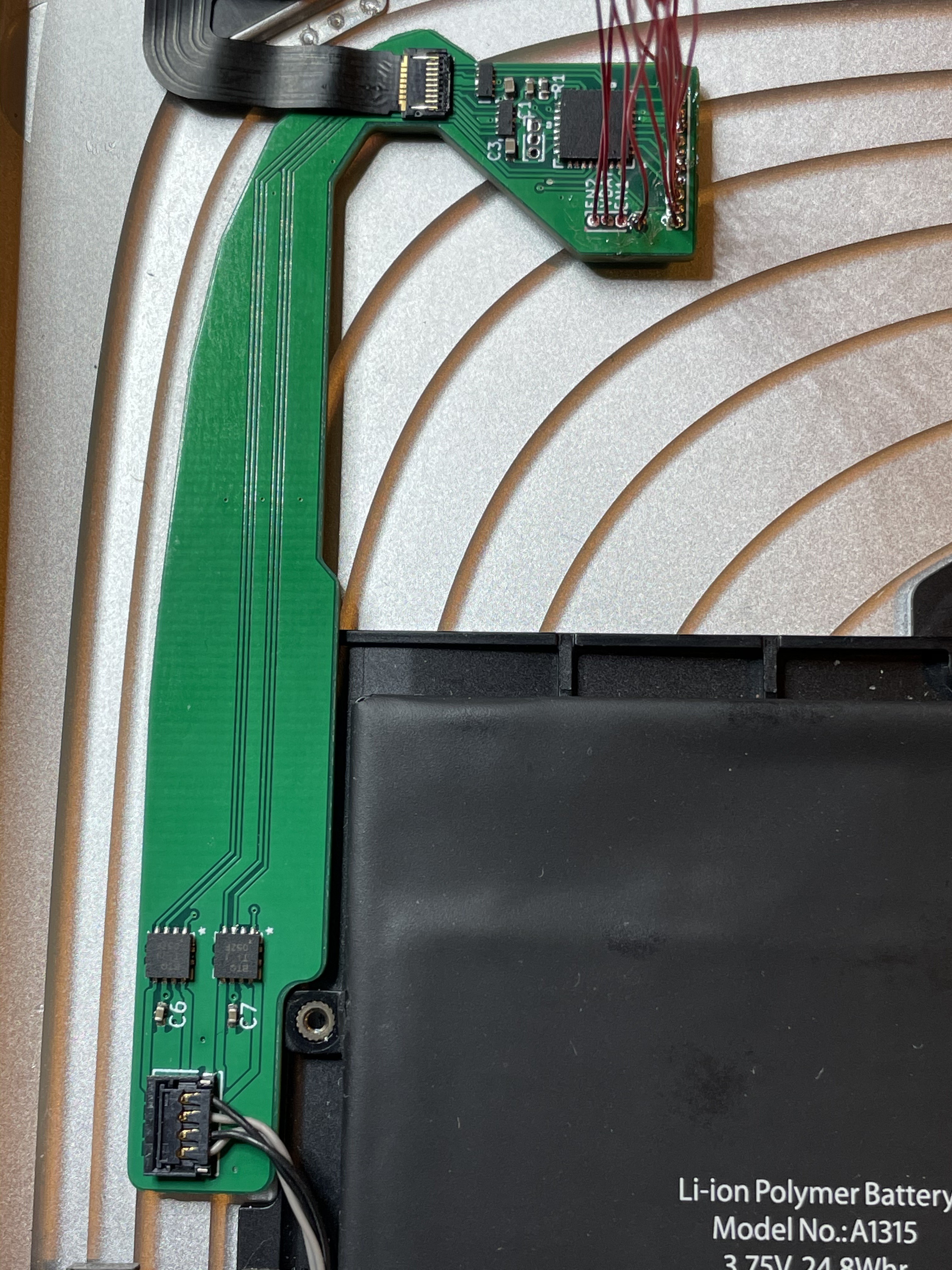
Looks like the connectors are in the right place / orientation, at least!
Still to do on the soundcard:
- Solder the other end of those magnet wires to some female header pins that can mate with the RPi 4 / CM4IO's 40-pin connector + something that can provide power.
- Test out the board.
Discussions
Become a Hackaday.io Member
Create an account to leave a comment. Already have an account? Log In.