 Evan
EvanSo I finally finished designing v0.0.1 of my PCB, and had them made by JLCPCB. This prototype has:
- touchscreen controller
- MIPI-DSI to LVDS converter
- LED backlight driver
- battery controller/boost converter
- audio codec, speaker amplifiers, and footprints for speaker and headphone connectors
- connectors for the 30-pin dock board and the ambient light sensor
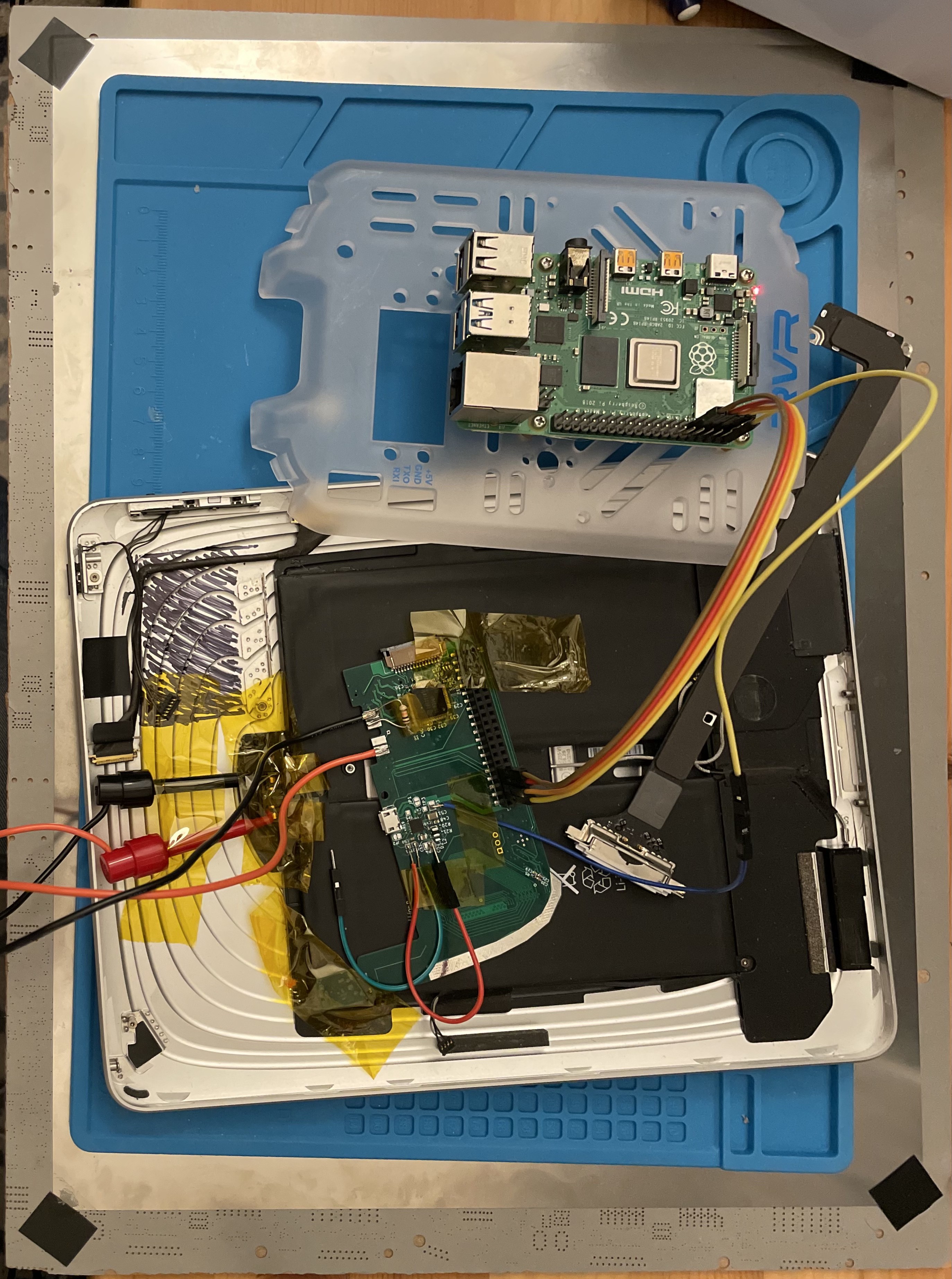
Instead of having the two 100-pin connectors for the CM4 like the final board will have, this version of the PCB is designed sort of like a Pi HAT, with a 40-pin header on the bottom. It also receives the video signal through a 15-pin ribbon cable, and has an extra USB micro B connector wired to the battery controller. This design allows for safer testing: I can connect only the pins that are needed to test one feature at a time.
I've assembled only the bottom of the board so far (the battery controller and the DSI-to-LVDS converter), and have been working on testing the battery controller.
My battery controller is adapted from Pi-Charger.sch from the SuperPower-RPi project, which is essentially the example schematic for the bq25895 battery controller from TI. In the SuperPower board, they use a separate boost converter to go from battery voltage up to 5V, but on my board I decided to use the bq25895's built-in boost converter, which can provide 3.1A at 5V if you add an extra diode. This approach has risks, and I will revisit this decision.
First thing I did to test it was give it 3.6V on the battery+ and ground connectors, hoping to see 5 volts output, but no dice. After scanning through the i2c registers, I eventually noticed that it was complaining about the thermistor being missing. After adding a 10k resistor... still no dice. Turns out I needed to pull the OTG pin high. Good thing I broke that out to a test pad!
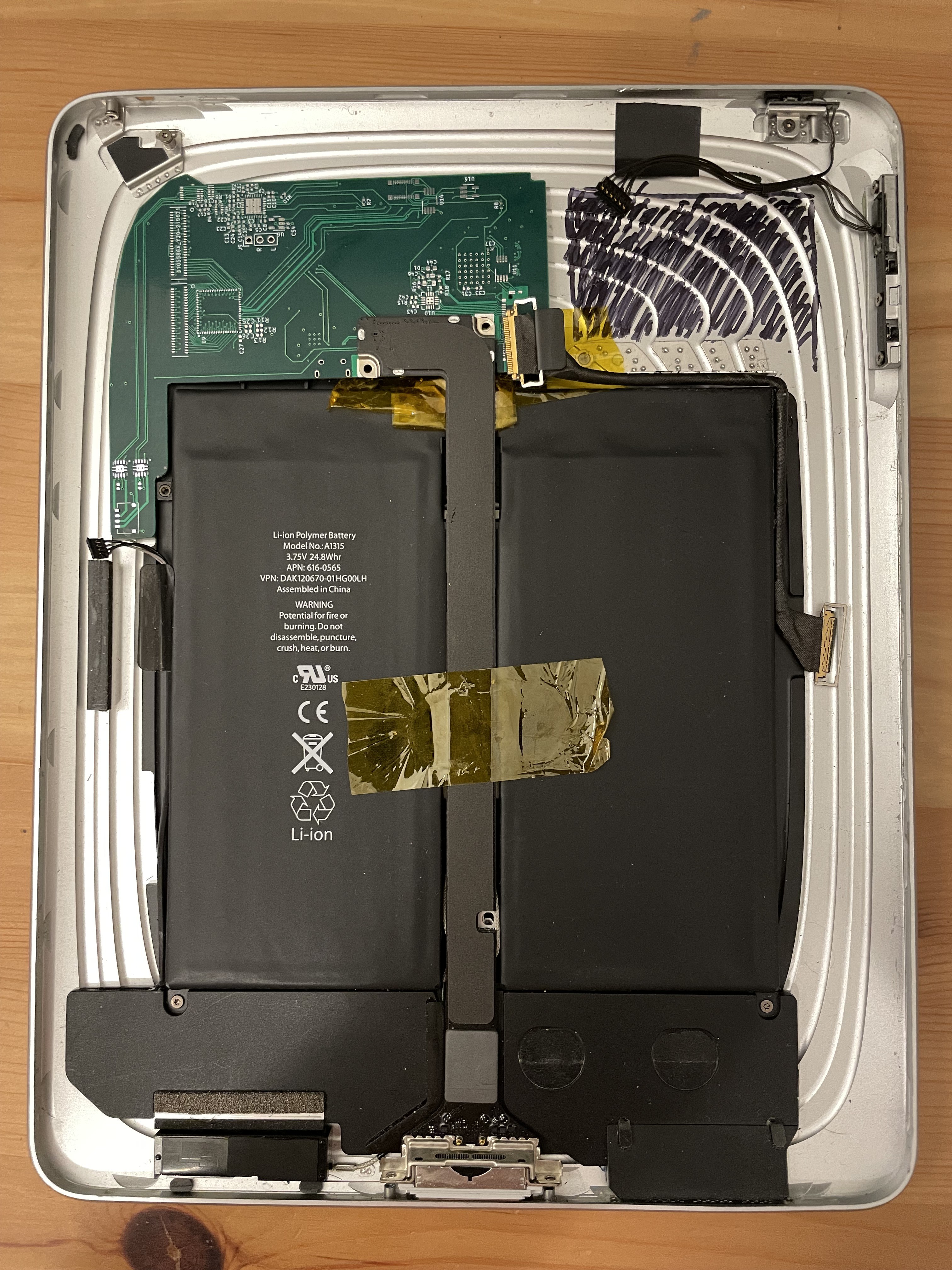
I futzed around for a while with various approximations of the iPad's battery (3x NiMH AA's in series; some old, fairly degraded 18650s out of a battery pack from a broken bike light). These all had too much internal resistance to supply the ~15 watt spikes required to boot the RPi 4, and would trigger the bq25895's undervoltage shutoff. Eventually, I gained enough confidence in the board to test with the iPad's actual battery. This worked great!
It seems like the iPad battery is in pretty good condition - at least, it's been holding a charge, and still has very low internal resistance. I measured maybe 50mV of voltage droop when booting the Pi 4.
Up next is probably testing the LED backlight driver, then after that I can test the LVDS controller. I may or may not be able to test the touchscreen controller: the FFC connectors are backwards. 🤦♂️
Discussions
Become a Hackaday.io Member
Create an account to leave a comment. Already have an account? Log In.