 Evan
EvanBased on my guess of how complicated testing the different components will be, I decided to test the LCD backlight controller next.
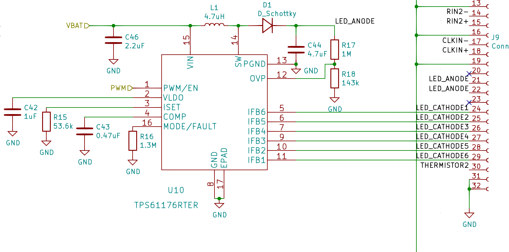
For this part of my PCB, I basically built the example circuit from the datasheet of the TPS61176. This chip is essentially a DC-DC boost converter and 6 constant-current/PWM sinks. You control it by providing a PWM signal on its PWM/EN input. It decodes this signal and then runs its own PWM on each IFB# pin.
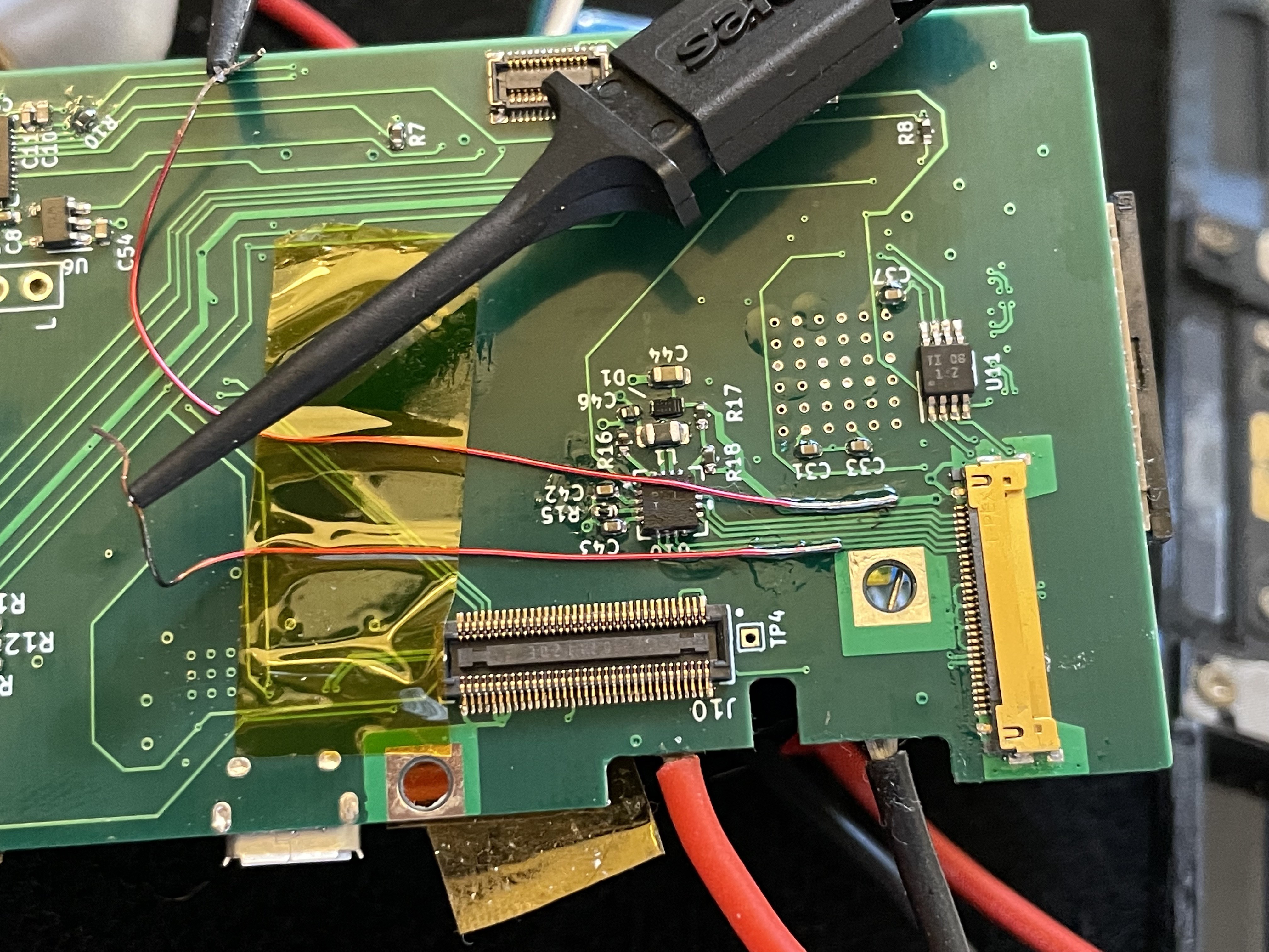
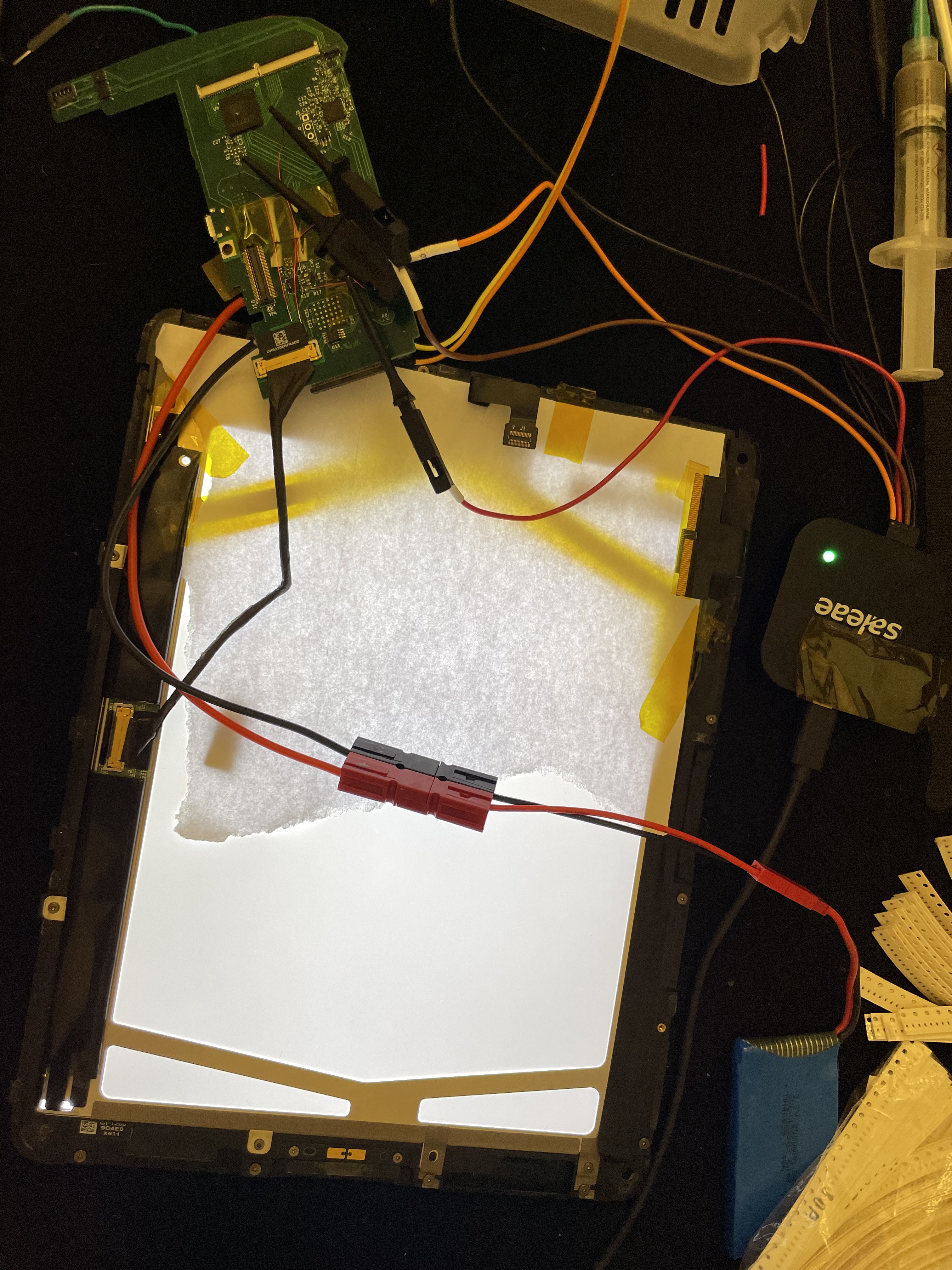
Not wanting to risk frying my iPad's display, I wanted to first test with my own string of LEDs. However, I'm a dummy and I neglected to put any test points on this part of my PCB, and because both ends of the trace end up at fine-pitch footprints, I opted to scrape away some solder mask and solder some magnet wire directly to some traces.
I dead-bug soldered a few LEDs together to make my test string, and connected them to the common anode and one of the cathode lines, which works great:
The TPS61176 will increase the anode voltage until your LEDs start actually drawing current, so it basically supports strings of LEDs with arbitrary forward voltage, within its voltage range.
After double-checking that I hadn't flipped the pinout for the display, I decided to connect the actual LCD panel. Powered it up and ....nothing. Black. The anode voltage was 3.6V (so, not boosted at all). My hypothesis is that it's detecting an open circuit on all the LED strings, so it disabled the boost converter. Some basic testing confirms:
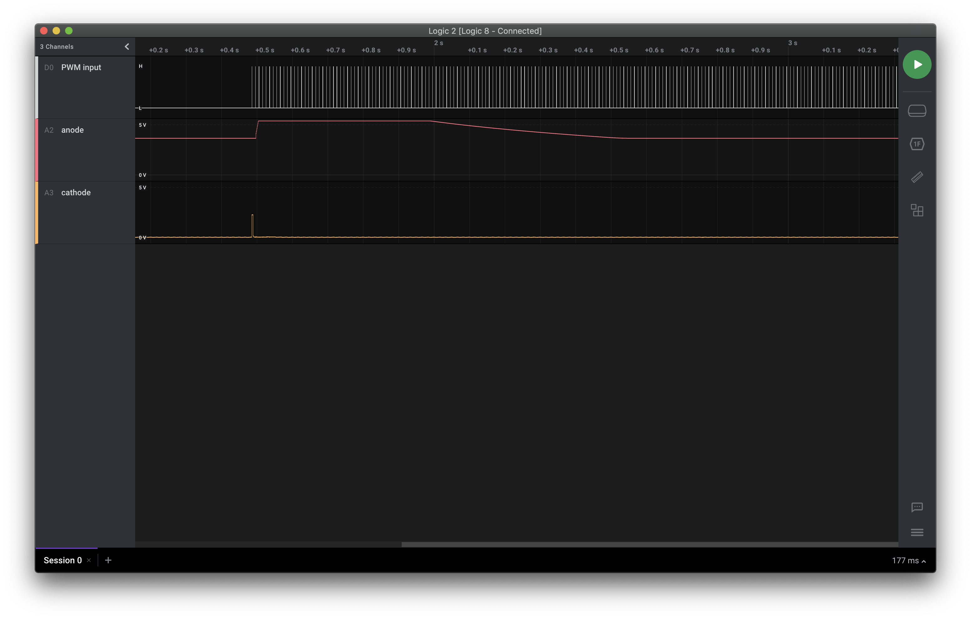
The anode voltage jumps (higher than my Saleae Logic 8 can measure), and then falls back down. I wonder how high that voltage is going? Is it higher than the 18V required to drive the backlight on the LTN097XL01-A01 panel in my iPad?
I soldered a few more wires onto my board: one at the MODE/FAULT pin, and one at the OVP pin (which is connected to a voltage divider with 143k / 1M, which divides the anode voltage by 8). Rerunning the test gives me:
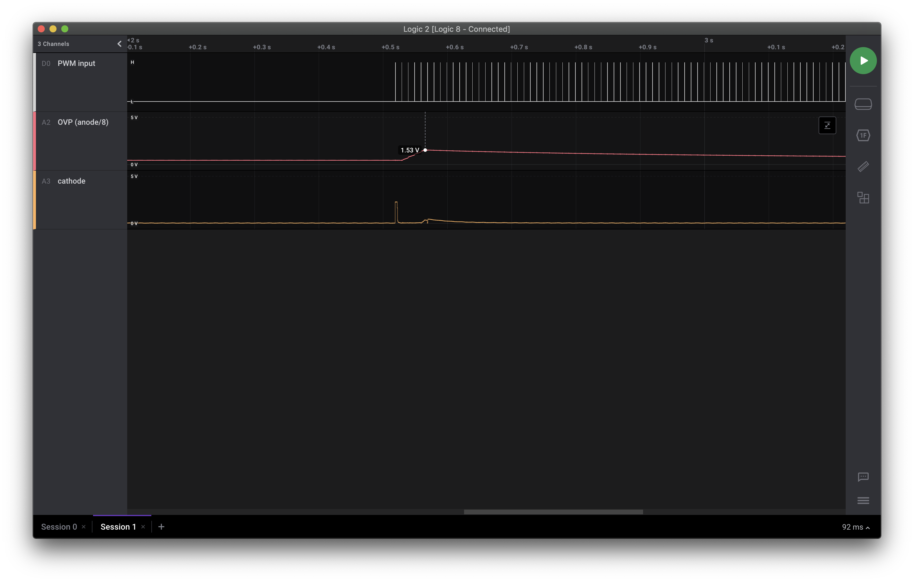
1.5V at the OVP pin. There's my problem! Turns out the reference voltage for the OVP pin is 1.5V, and with the 1/8 division, I'm only getting 12V max. I need to adjust the ratio on my voltage divider.
After swapping the 143k resistor for an 82k resistor, the backlight works!
Discussions
Become a Hackaday.io Member
Create an account to leave a comment. Already have an account? Log In.