deftcoyote
The images of the original come from https://www.earlycomputers.com/cgi-bin/item-report-main.cgi?20110802, https://www.earlycomputers.com/cgi-bin/item-report-main.cgi?20110802, and http://www.vintage-icl-computers.com/icl48i. Other than a few random images, these are the only sources of information I've found on the device. None of them have the manual shared (they only share ad material).
0%
0%
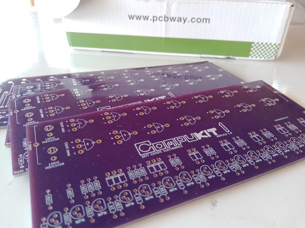
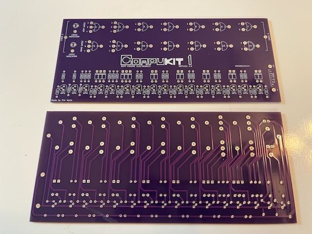
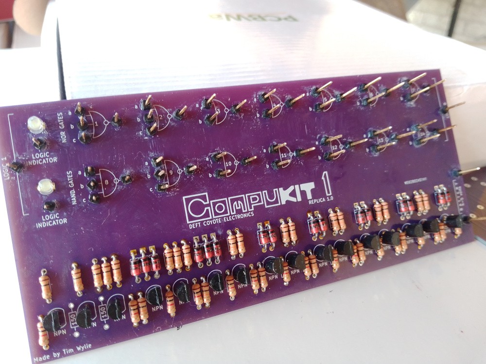
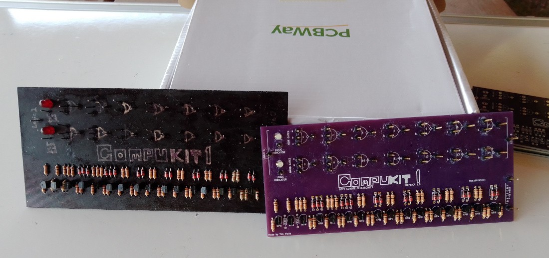
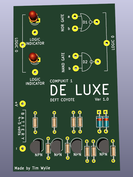
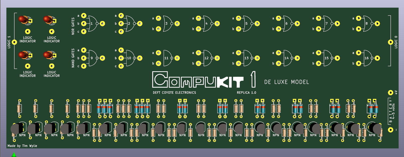
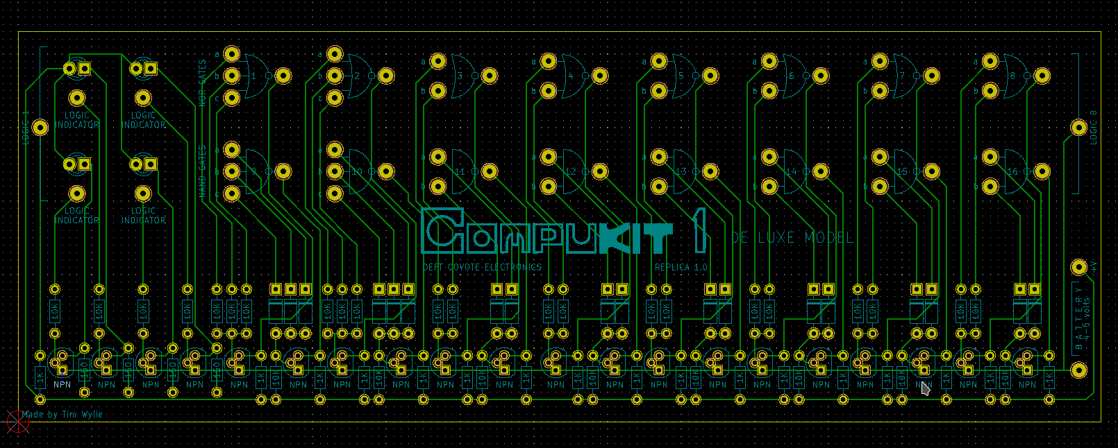
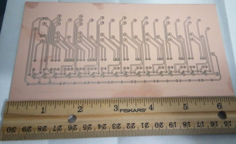
Limrose Compukit 1
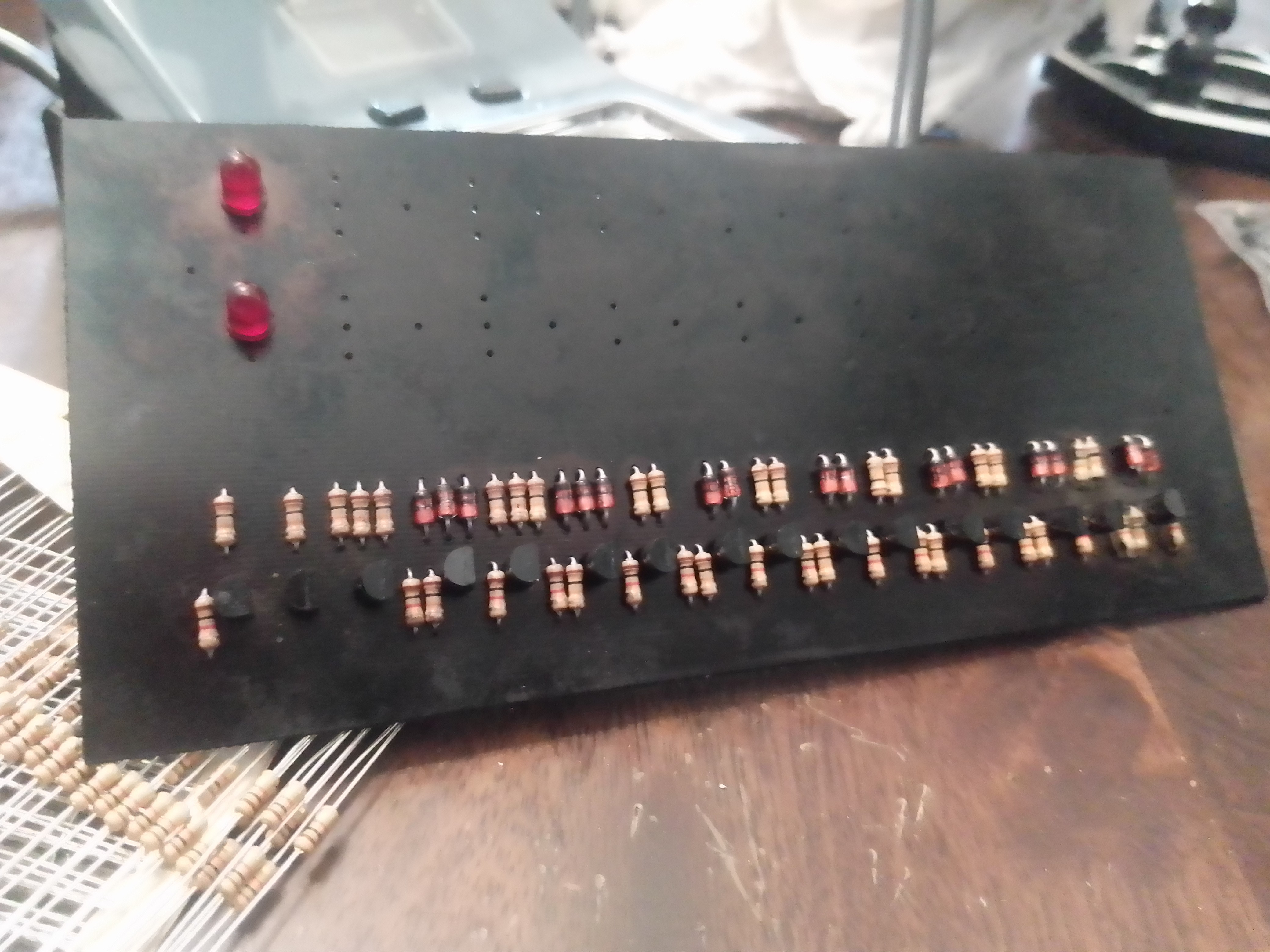
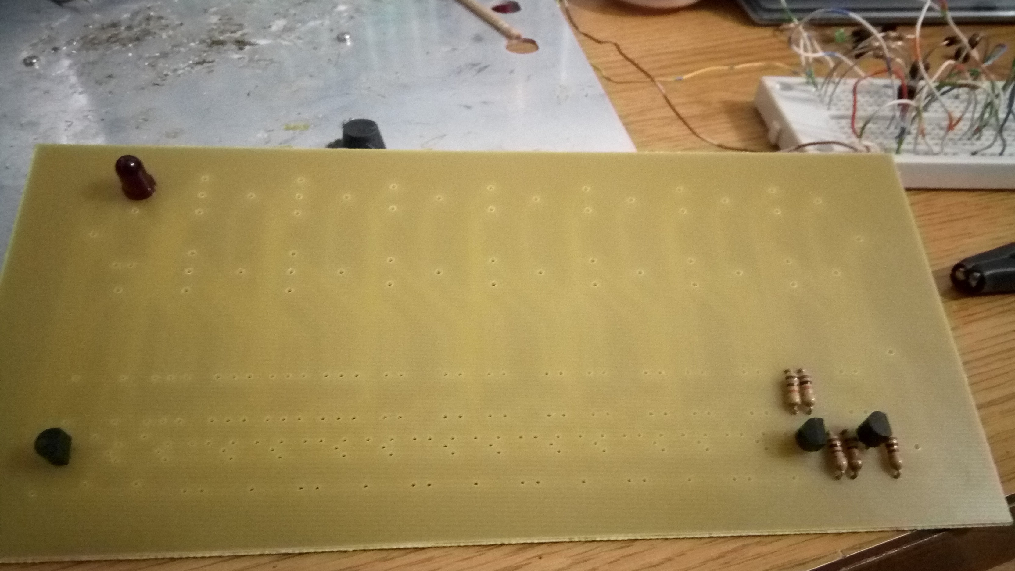
Recreation of the Limrose Compukit 1 from 1970.
Become a Hackaday.io member
Already have an account? Log in.
Just one more thing
To make the experience fit your profile, pick a username and tell us what interests you.
Pick an awesome username
hackaday.io/
Your profile's URL: hackaday.io/username. Max 25 alphanumeric characters.
Pick a few interests
Projects that share your interests
People that share your interests
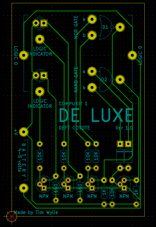
 I added the additional needed components to the Component section with a "for Deluxe" after the component to identify them as separate.
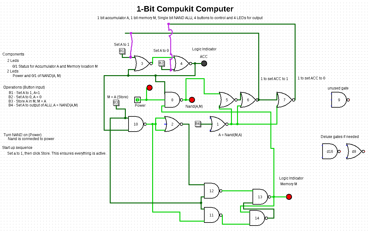

 Ken Yap
 Torbjörn Lindholm