 deftcoyote
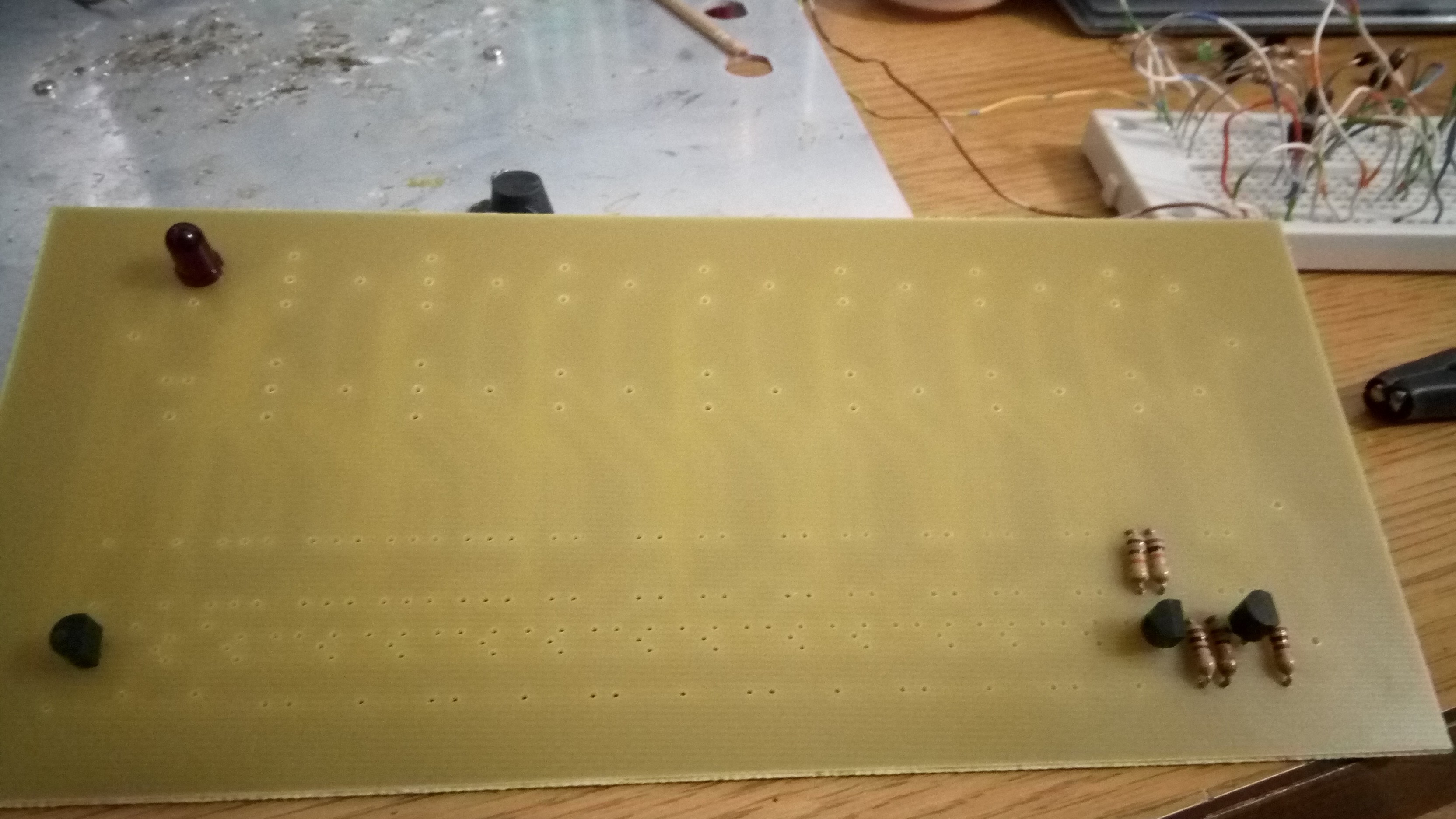
Well, I double checked some components and wiring, and started soldering the main board together. Unfortunately, I only have a few diodes, so I only soldered a couple of the components to test whether the gates were working correctly. I'm ordering some more.
Here's the start:
And you can see some of the testing.
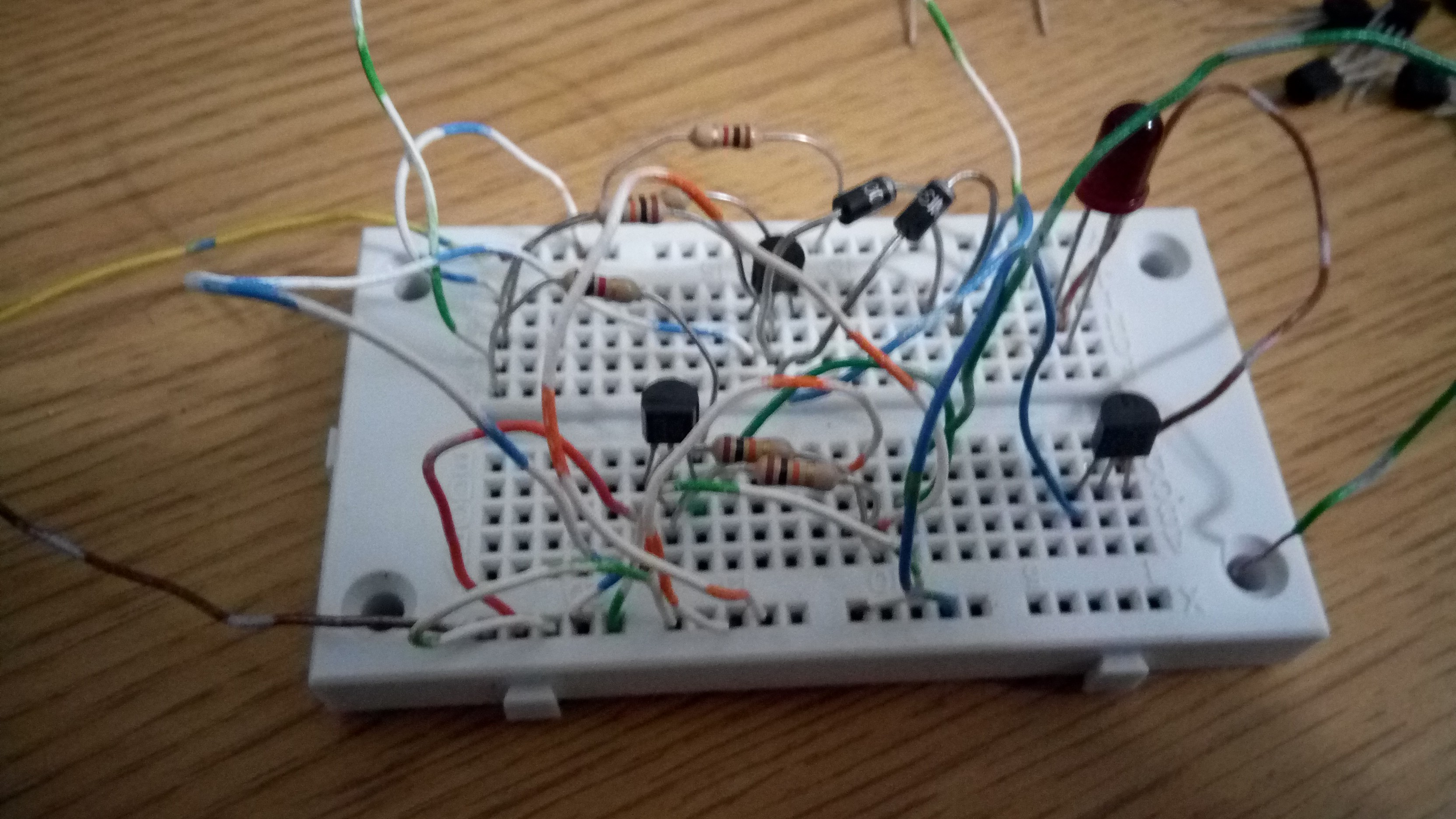
I was expecting this issue with the LEDs, but it's still annoying. The original Compukit used bulbs, and the transistor expected voltage on the base to connect it to ground for it to light up. It also had a 150 O resistor straight to ground. With an LED, it stays lit up unless you put > 1 M resistor there. The best plan, I believe, is to remove the two 150 O resistors altogether.
Also, the 10K resistor on the base (the logic indicator allowing the LED to light up), seems to be too great. Although, I was testing with around 3.5 volts. So I may reduce that resistor as well, but I need to test a bit more.
I will update the board and schematic once I determine the best values for the LEDs, and I think it may be possible to simply remove the two grounding resistors. The only problem with this is that there's no resistor coupled with the LED going to ground if you directly touch the logic 1 probe to the logic indicator, so one might need to be added between the LED and the transistor rather than it's current design.
Discussions
Become a Hackaday.io Member
Create an account to leave a comment. Already have an account? Log In.