 deʃhipu
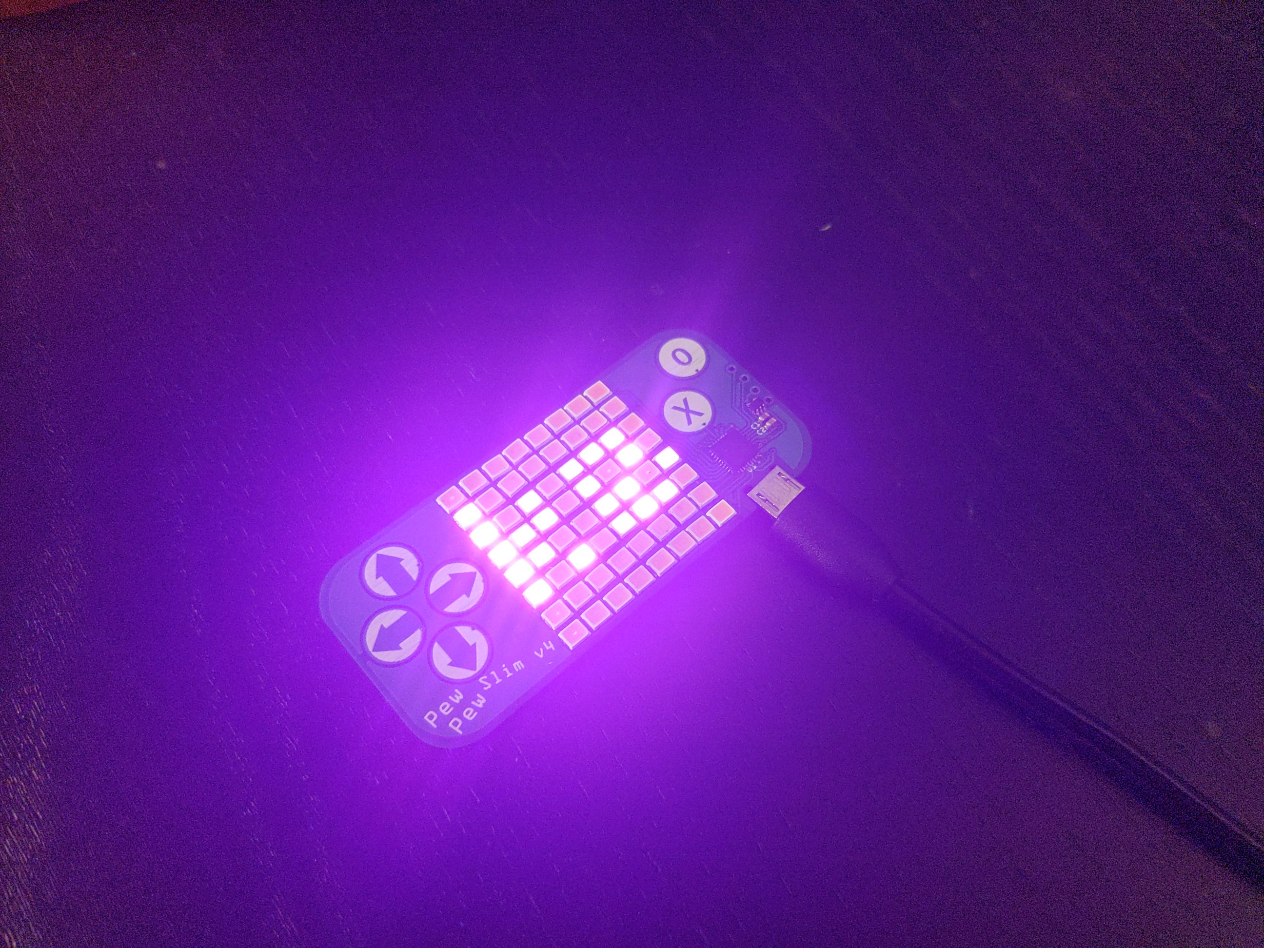
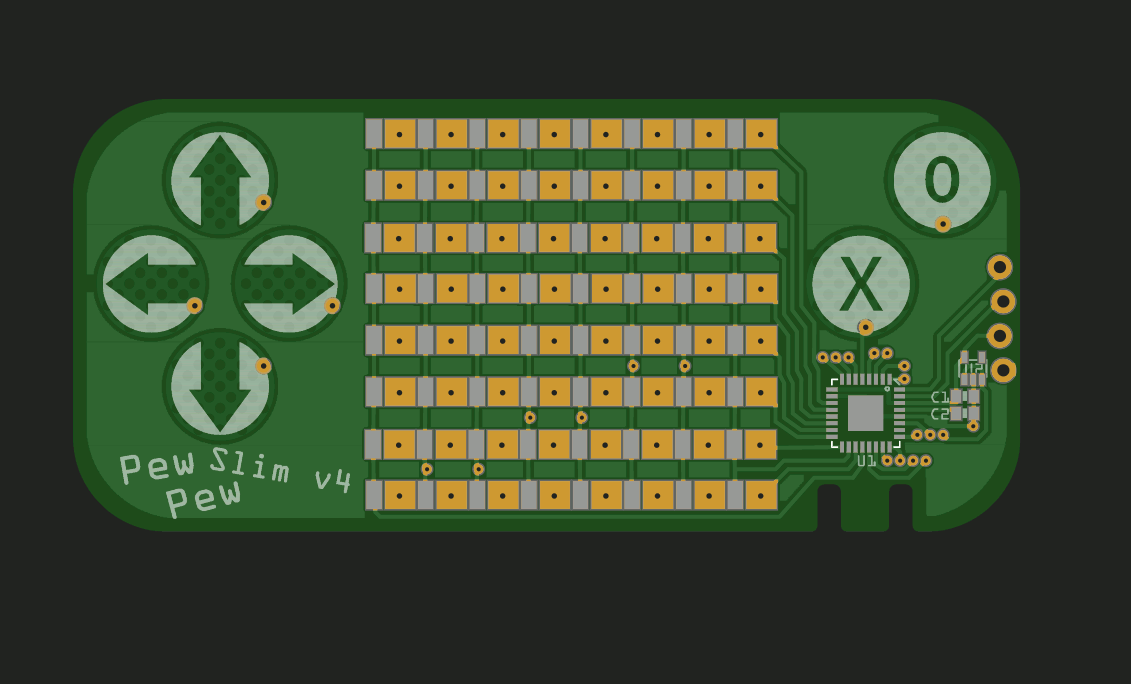
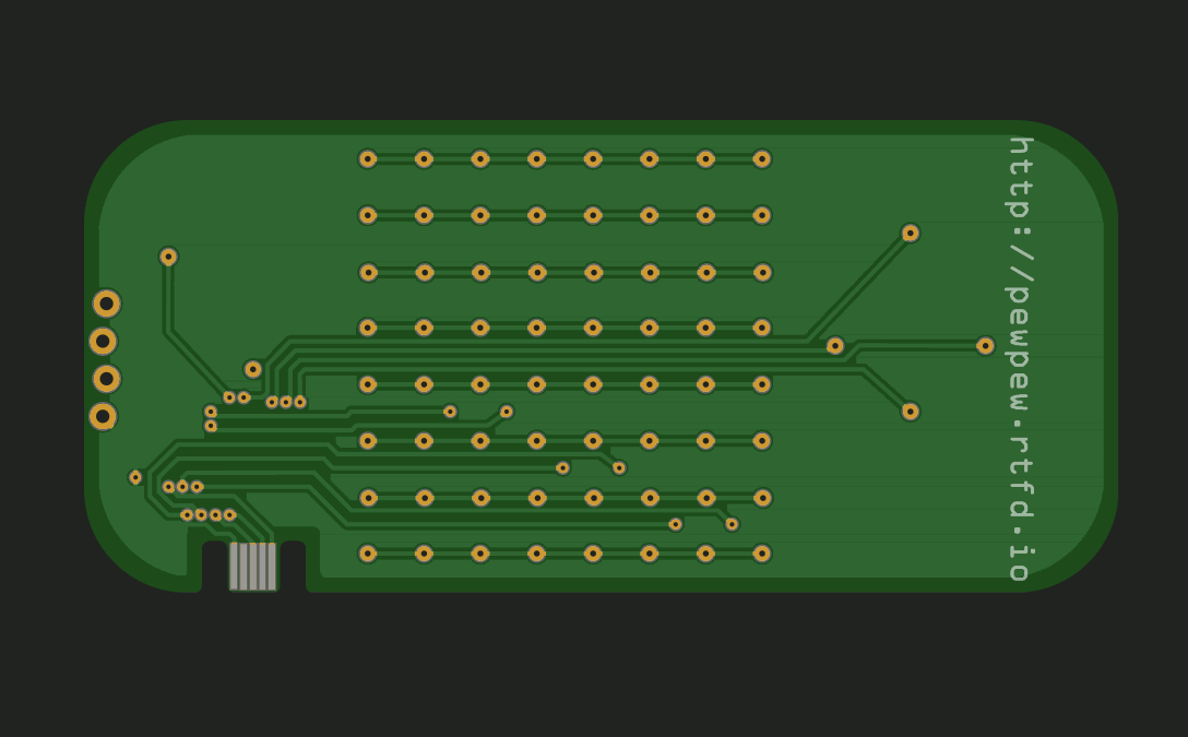
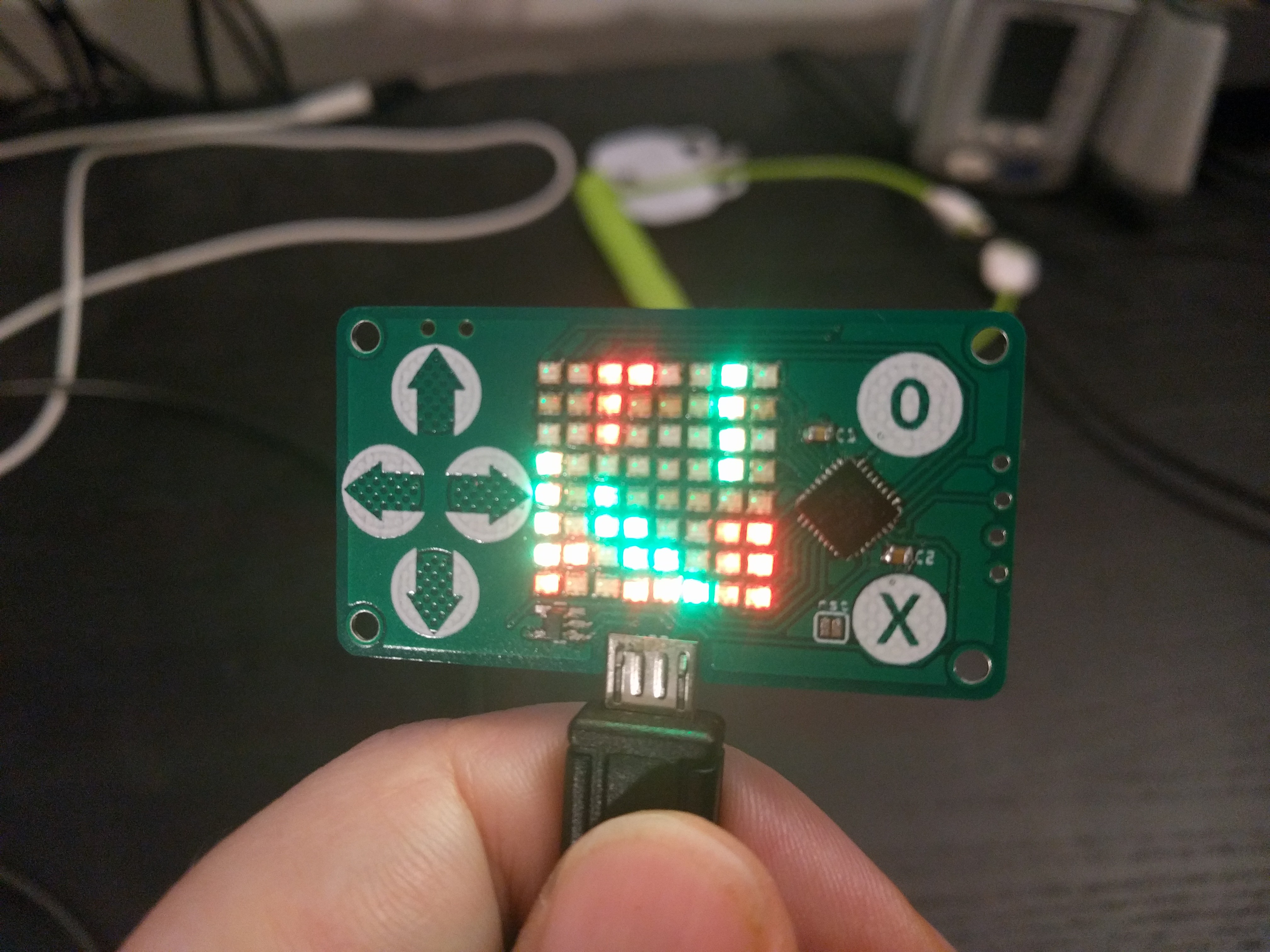
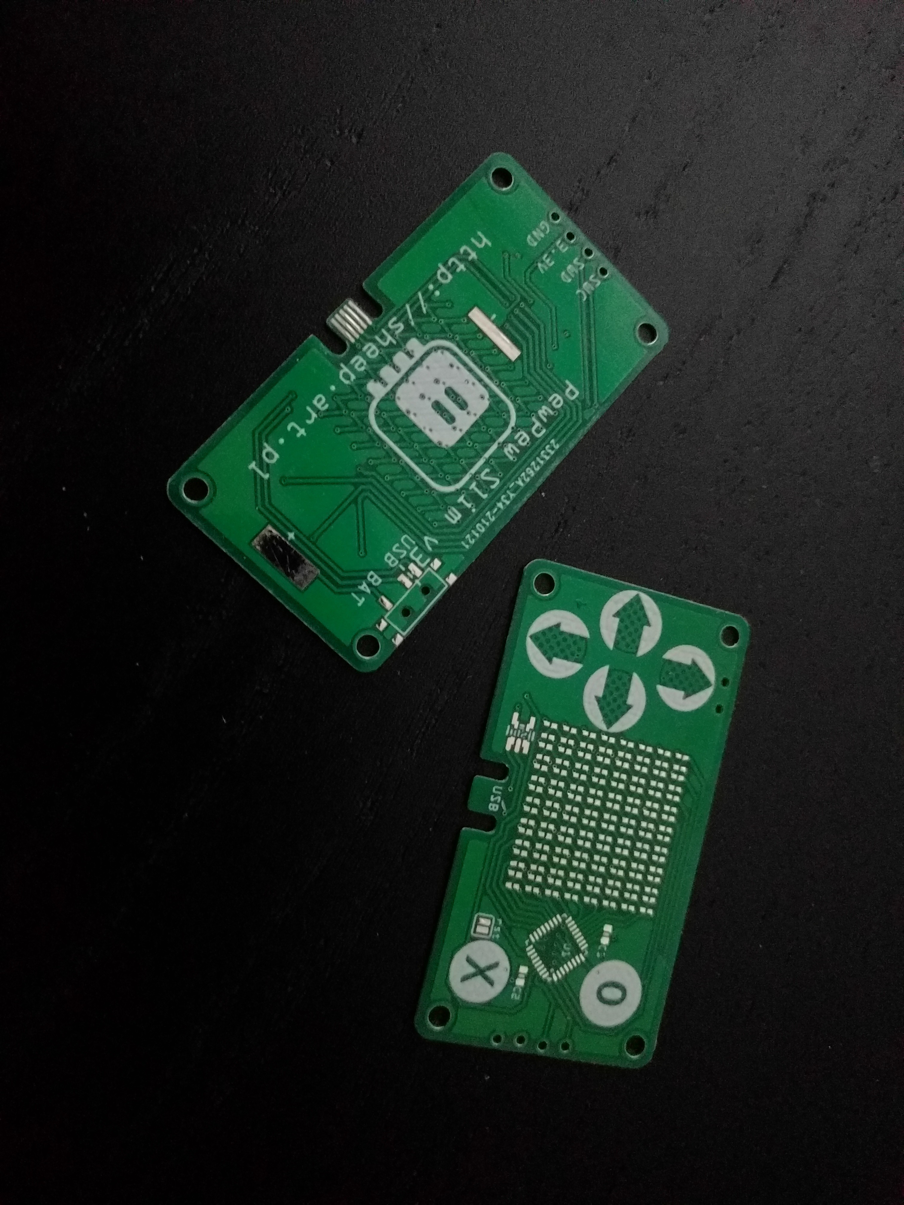
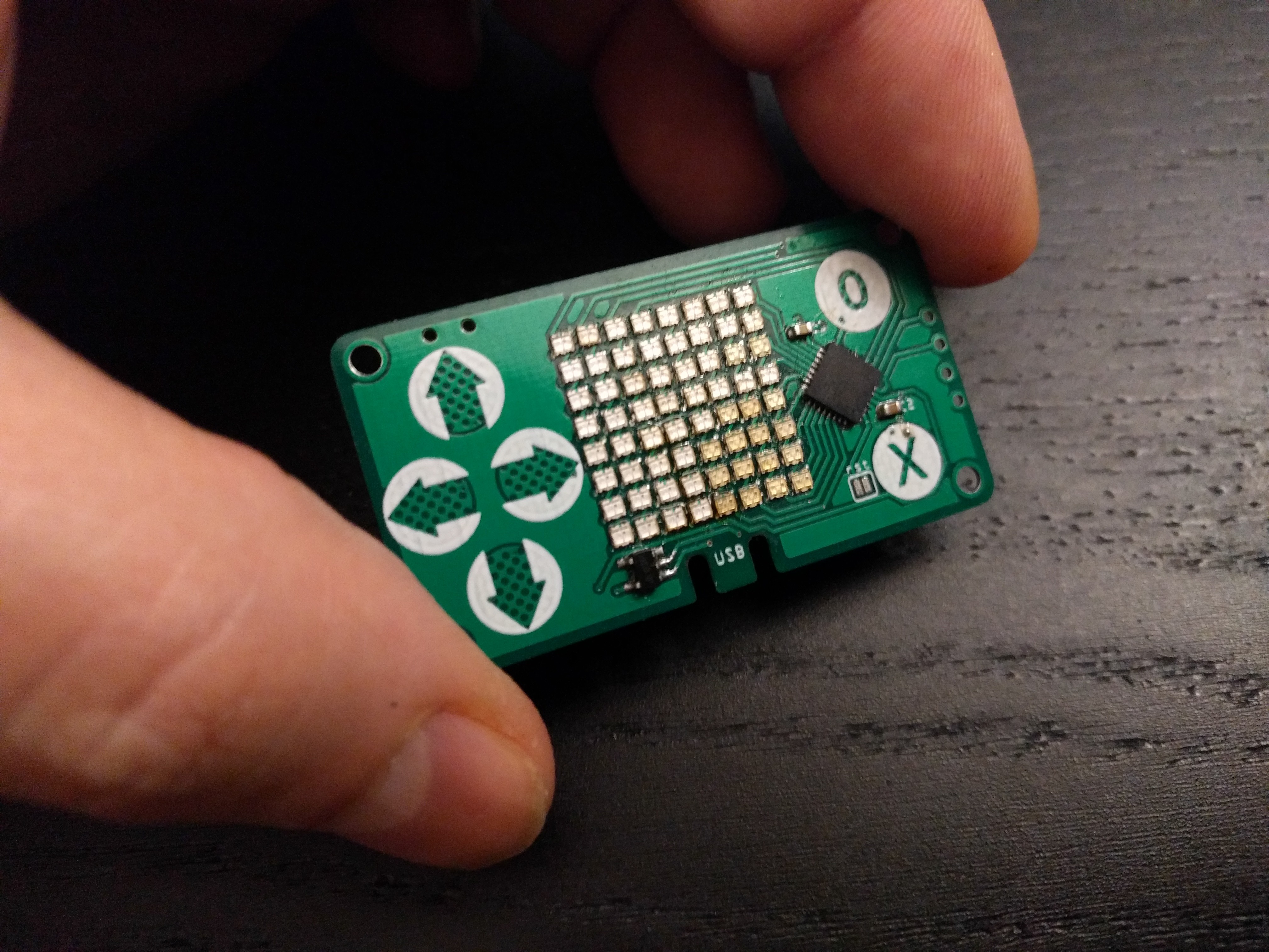
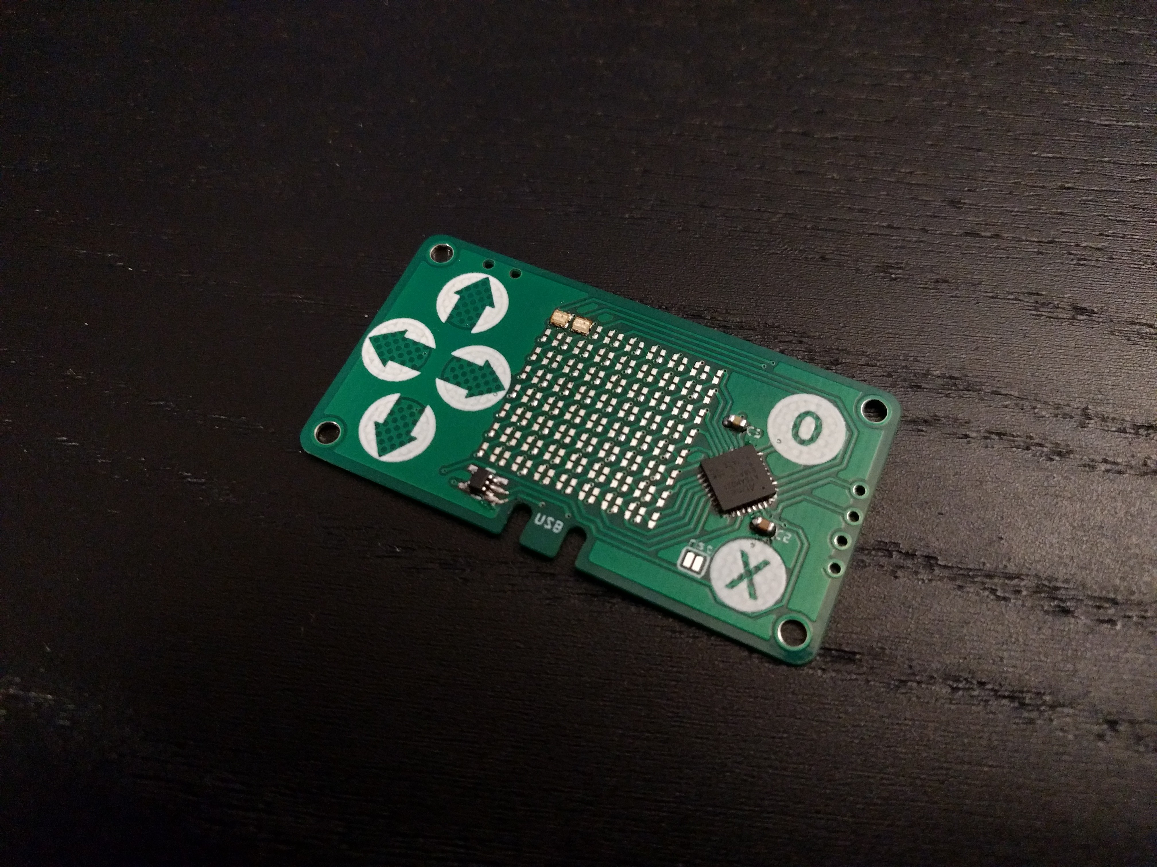
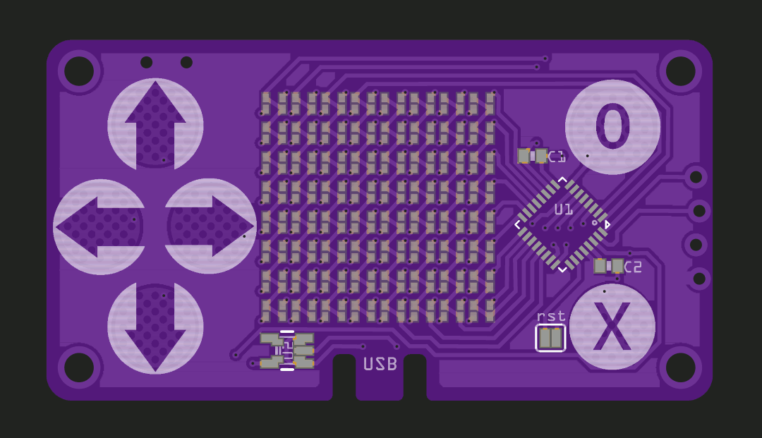
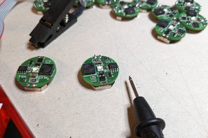
The #PewPew Standalone is optimized for cost, and since that means that you want to do as little soldering as possible, it uses a ready LED matrix as a single component. However, if you instead use discrete LEDs, replace the buttons with touch pads, the USB socket with a 0.6mm thick PCB cutout and drop the battery and power switch, you can get something really thin — below 2mm total. Something that could possibly be used as a business card.
0%
0%
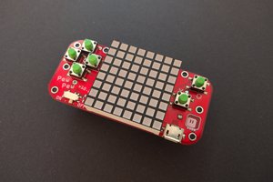
PewPew Slim
PewPew in a business card form factor.
Become a Hackaday.io member
Already have an account? Log in.
Just one more thing
To make the experience fit your profile, pick a username and tell us what interests you.
Pick an awesome username
hackaday.io/
Your profile's URL: hackaday.io/username. Max 25 alphanumeric characters.
Pick a few interests
Projects that share your interests
People that share your interests


 schlion
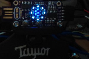
 rrace001
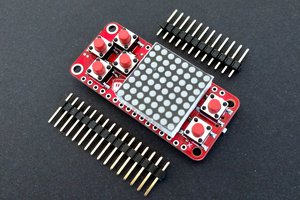
Awesome stuff my man. I am BiggestGuy and I approve this project.
I reckon if you could maintain this form factor and find a way of implementing user interaction you could create a sort of business-card-sized remote control. With something like a membrane top with metal underneath (in the same sense as a membrane keyboard) it could make for a pretty interesting and ergonomic system that could be paired to other projects.
either way its super cool!