0%
0%
7 Segment Display Module using DM9368N
Handy 7 seg module that crams two DM9368N and two digits onto a single board that I can plug in on my breadboards.
 John Lonergan
Become a Hackaday.io member
Already have an account? Log in.
Just one more thing
To make the experience fit your profile, pick a username and tell us what interests you.
Pick an awesome username
hackaday.io/
Your profile's URL: hackaday.io/username. Max 25 alphanumeric characters.
Pick a few interests
Projects that share your interests
People that share your interests


 Stephen Holdaway
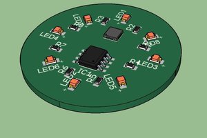
 Luc
Luc
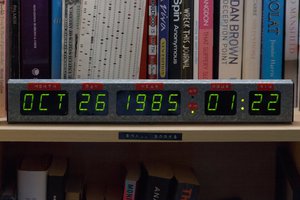
What on earth are you planning to do with them? Crash the market for them on Ebay or something?