The tuning fork clock
I got the inspiration for this project after reading this article on another tuning fork clock on Hackaday last year. And since I was, at the time, burdened with an overly loud mechanical clock on my desk I thought that this might be a perfect project to replace that clock with something just slightly less annoying.
Designing the oscillator
I really liked the general concept and started doing some experiments on how to build my own tuning fork oscillator. While I liked the idea of driving the fork magnetically as in the original project I thought it would be much nicer to also sense the vibration magnetically.
Of course the tuning fork doesn't have it's own magnetic field so I designed a 3D printed holder which would contain both the inductors which I use as driving and sensing coils and a neodymium magnet which would generate an external field. Similar to a guitar pickup the motion of the tuning fork inside that field generates disturbances which can be picked up by the sense coil and amplified.
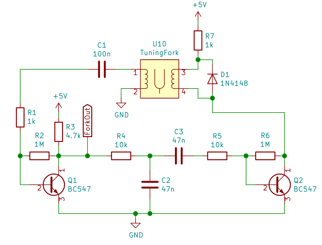
I needed a way to add positive feedback between the sense and drive coil to keep the tuning fork going, so I designed a simple transistor based amplifier circuit that integrates some filtering to minimize harmonics.
The output of the sense coil is amplified by a single stage common emitter amplifier and filtered by a passive bandpass filter centered roughly around 440Hz. From there the signal is fed into a second transistor amplifier which powers the drive coil.
This circuit is surprisingly effective and is able to sustain the oscillation of the fork down to less than three volts while drawing around 1mA. When running at 5V, like in the finished clock it's also sensitive enough to be self starting, eliminating the need to tap the fork to get the clock going.
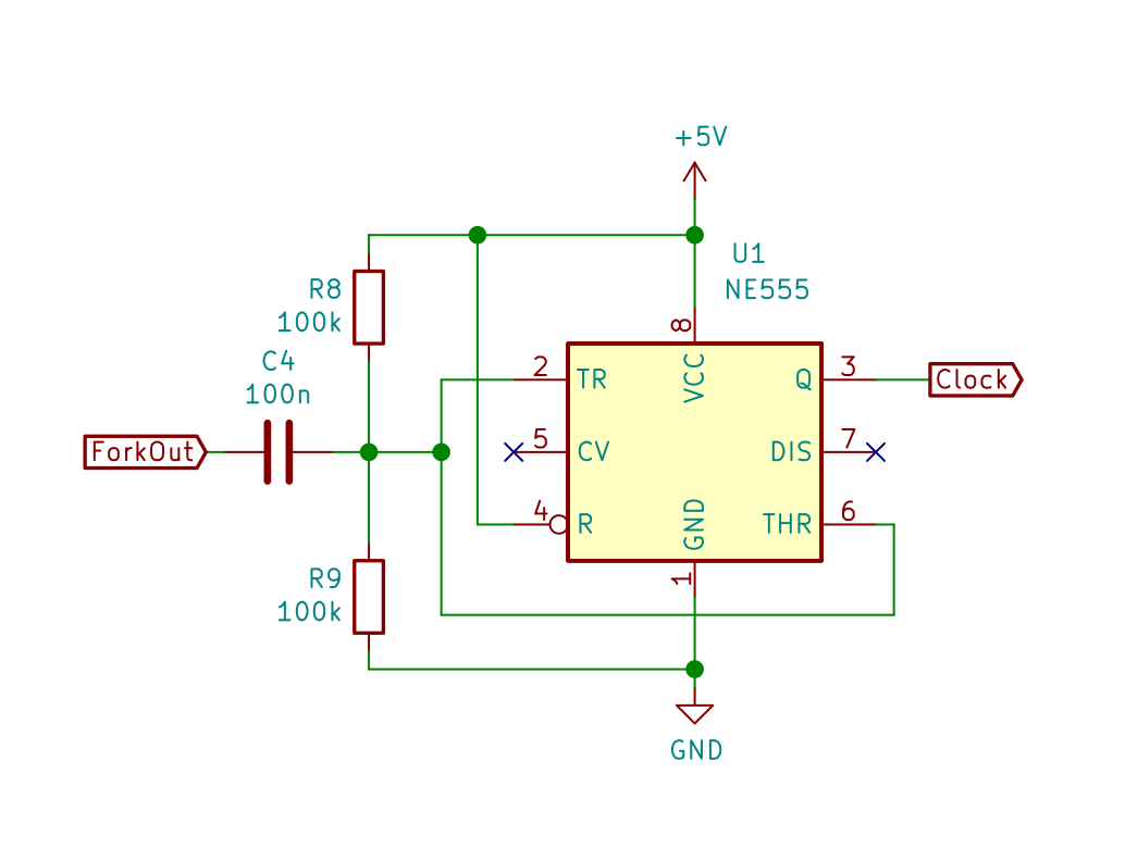
As a last step the signal from the sense coil is also fed into a 555 which ensures that the analog signal from the sense coil amplifier is suitable for a digital input pin on a microcontroller.
Digital section

The digital section of the board consists of an ATTiny4313 and a 74HC595 shift register. The ATTiny4313 uses one of it's timers to count the oscillations of the tuning fork and handles serial I/O and a push button rotary encoder for user input. The 74HC595 is used to shift out the data to be displayed on the 5 multiplexed 7-segment displays.
A set of three LEDs (not shown in the above schematic) are used to give feedback to user inputs and display the current status of the oscillator.
Firmware
The firmware is written in C for the avr-gcc compiler. I originally started out with a ATtiny2313 microcontroller but realized I'd need more flash storage to implement the serial control protocol I envisioned, so I switched to the larger ATtiny4313.
The main timekeeping work is done by a timer which counts the number of pulses coming from the tuning fork oscillator. Two overflow events are generated from this, one roughly every second, and one every minute.
I decided to count the number of pulses per minute and use that as my main source of timekeeping since the larger number of pulses would allow for finer adjustment of the speed the clock runs at. The second interrupt is used for giving a rough approximation of the progress of the minute, a blinking second indicator and a pulse per second signal.
A second timer takes care of the display scanning and update, monitoring of the oscillator signal and various other regular tasks like input timeouts and display blink animations.
The main loop of the program handles non timing critical code like serial input and output, parsing incoming commands and executing them. When no further work is available the processor goes to sleep to save on power.
Character Set
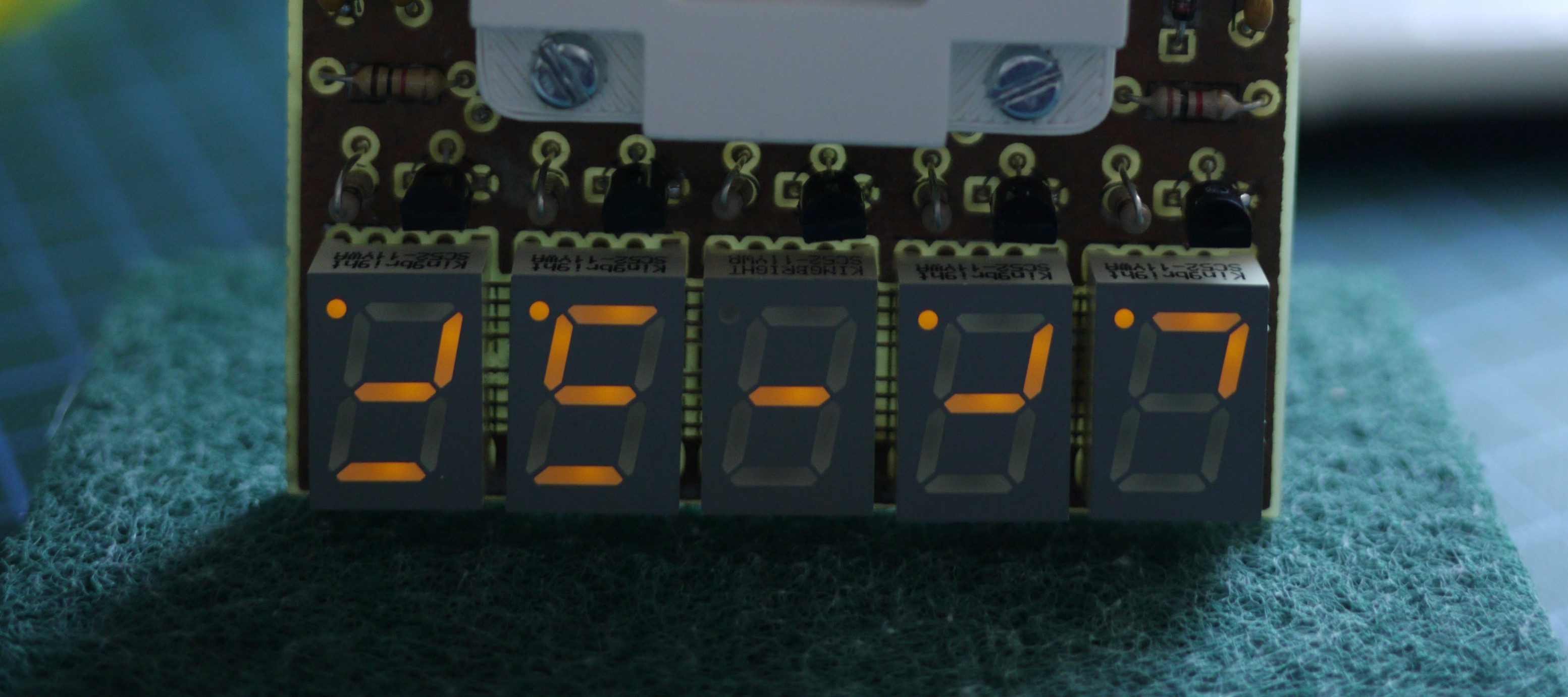
To accentuate the unusual look of this clock I decided to make use of a writing system I originally developed for calligraphic purposed and personal note taking many years ago. It is a simplified version of the Elian Script which only has one possible way to write each character.

Since numbers in my writing system only make use of four possible lines and a dot it was easy to adapt them to a 7 segment display. To allow the dot to be placed closer to the numeral I flipped the displays upside down, allowing me to display numbers on the upper 4 segments of the display and leave the lower part for displaying a kind of "progress bar" of the current minute.
PCB design and assembly
I designed the circuit and PCB using KiCAD, and with this being a kind of weekend project (which turned out to be more like a whole week project in the end) I wanted to tackle etching this circuit board myself.
To accommodate for this I took care to keep my track spacings as wide as possible and avoid unnecessary vias by making use of existing pins to jump layers whenever possible while keeping accessibility when soldering in mind. Since my home made PCB wouldn't have plated through holes and some components like DIP sockets would obscure the top of the board I had to take that into account when designing my board. All the required vias were enlarged so I could make connections using a piece of wire through the hole.
For the etching itself I transferred my design onto a double sided bare copper clad FR-4 board using a cold toner transfer method using nail polish remover. I aligned the two printouts, taped them together and slid the cleaned board between them before soaking both sides in nail polish remover and applying pressure until the nail polish remover had evaporated. After soaking the paper in water I removed it carefully, leaving the toner behind as etch resist.
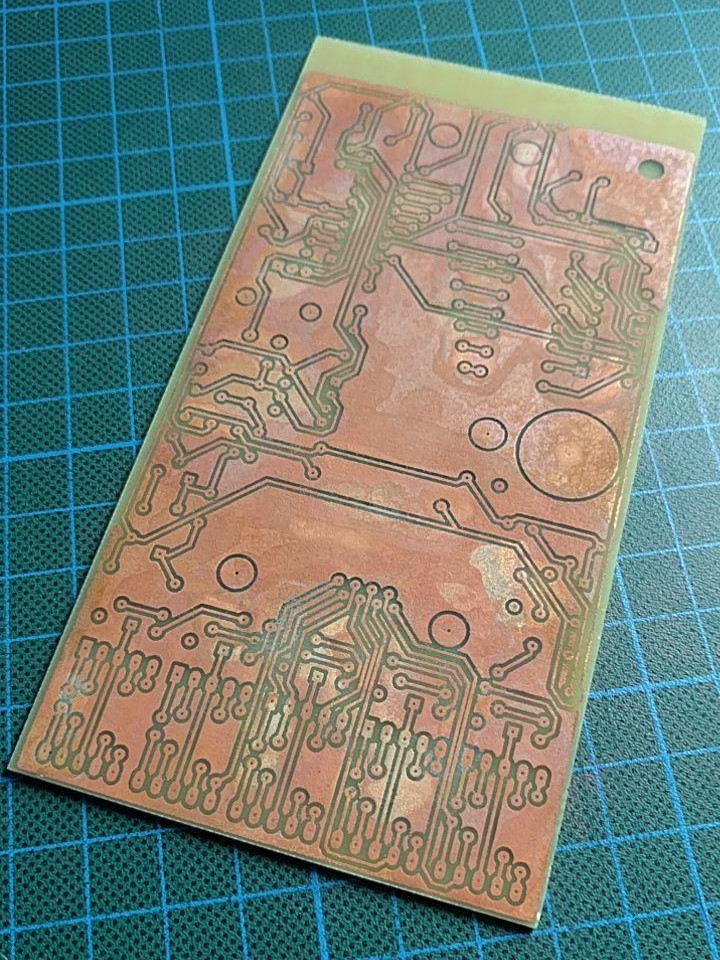
The actual etching was done using a mix of 10% acetic acid, 1% of sodium chloride and 1% of hydrogen peroxide in distilled water. While slower than using ferric chloride this method is nice cause it can be done using materials readily available from most grocery stores and pharmacies.
The etching took around 30-45 minutes and worked reasonably well. Considering this was my first large double sided board I had ever etched I was very happy with the outcome. Some of the etch resist got scratched off by a bump in my etching tub, so some connections had to be fixed by hand later.
Worthy of note is that my hydrogen peroxide (12% for use in hair salons) contained a chelating agent meant to stabilize it but this readily reacts with the dissolved metal ions and falls out of solution as fluffy white precipitate. This didn't seem to do much harm to the etching process, but was kind of a mess.
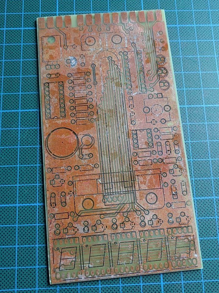
After the etching the front silkscreen was applied using another round of cold toner transfer to help with the assembly.
All 3D printed parts required to hold the fork and coils in place were designed in FreeCAD and 3D printed. After mounting the fork to the PCB I assembled the powersupply and analogue sections and after confirming the correct function of the oscillator the digital section was added.
The end, tl,dr
It's a pretty cool clock. It hums quietly instead of ticking. It's more accurate than I thought, within a couple of seconds per day after tuning it.
Wanna make your own? It's all open source! Circuit diagrams, PCB files and firmware is all on GitHub!
 Kris Slyka