 Mario Ninic
The 465A amplifier was published in the 1966 HP journal on the page 14.
https://www.hpl.hp.com/hpjournal/pdfs/IssuePDFs/1966-07.pdf
The original service manual with the schematic can be found here:
https://literature.cdn.keysight.com/litweb/pdf/00465-90003.pdf?id=1874185
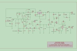
In this project I copied the original schematic with the exception of the power supply section which I replaced with the LT783 regulator. For the transistors I use 2n2608 for the Q1, BC546B for Q2, Q3, 2n3053 for the Q4, Q5 and 2n4037 for Q6.
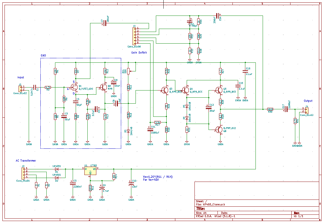
Here is my KiCAD schematic diagram.
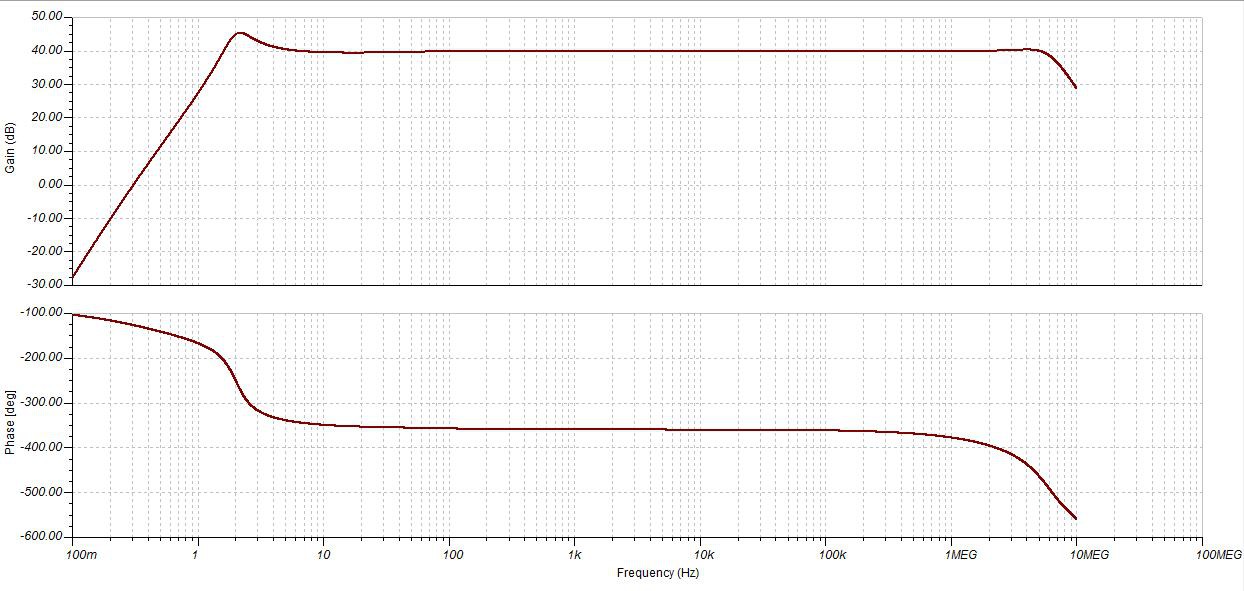
I simulated amplifier circuit using TI Tina software and I have to tweak couple of components to match original frequency response.

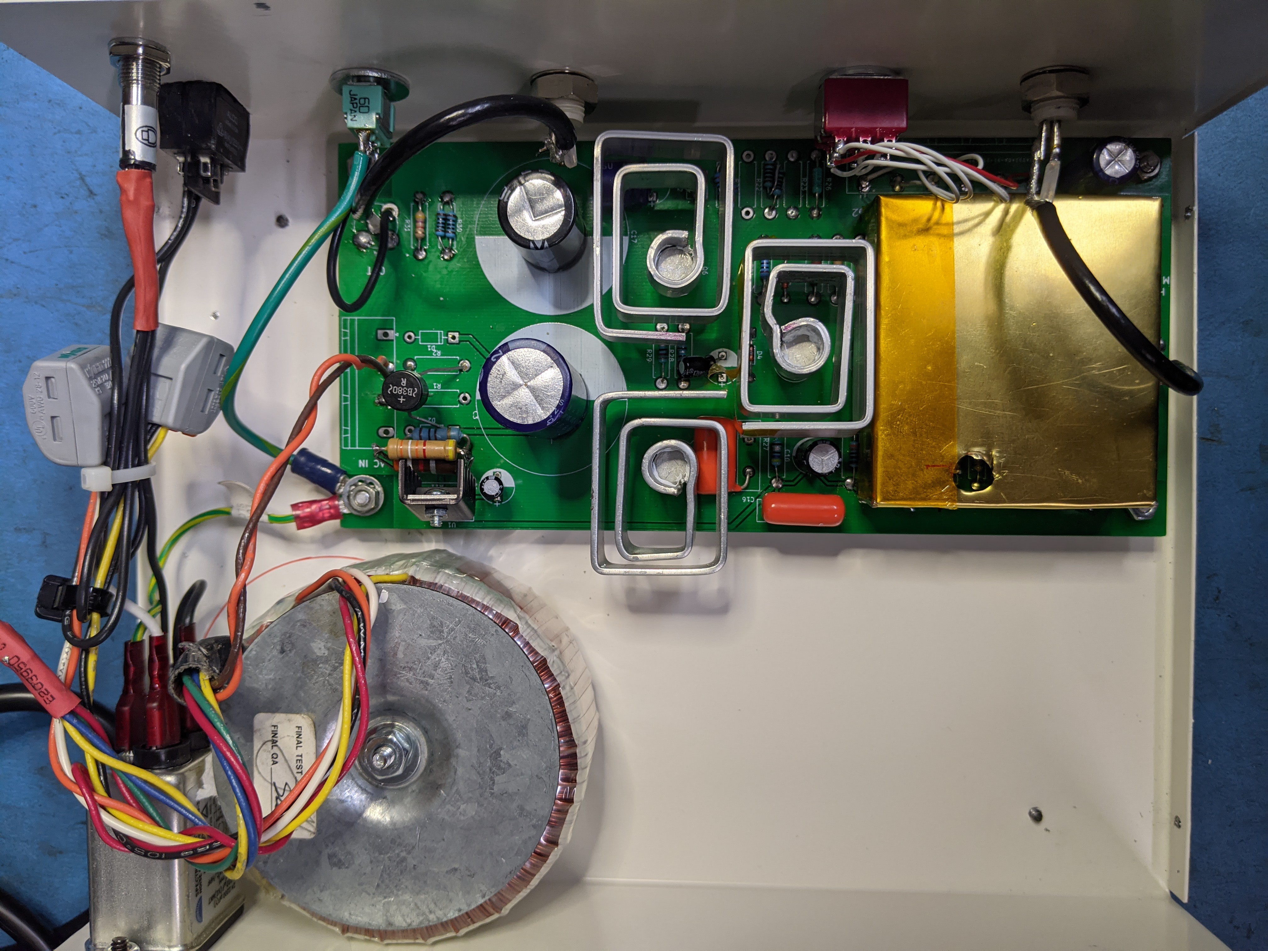
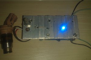
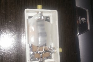
I have to update transistors heat sinks and I did some DIY with aluminum. Test results with the new heat sinks are great and the transistors are at 35Deg C after 4 hours of run in enclosed box.
Preliminary frequency sweep:
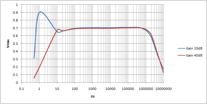
More test data coming soon.
 Scott Bragg
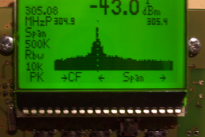
 Tiago
Tiago