 Amey Dahikar
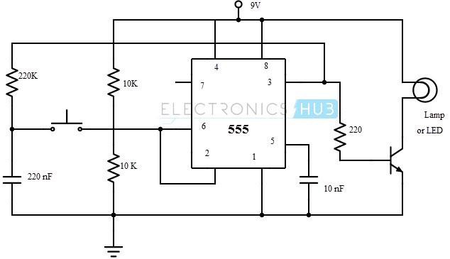
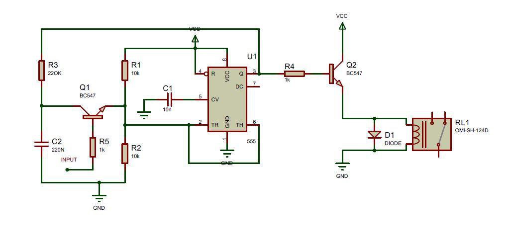
Its operation is simple as the 555 working as flip-flop its store the previses state of input and the output change each time when input gets changes
The 555 timer in bistable mode i.e. as a flip-flop can be used in low speed, non-computer applications like robotics. A simple application is a robot which moves forward and backward every time it hits an object.
 Albert Gonzalez
 Andrea De Napoli
 Discrete Electronics Guy
 Bruce Land